So, looking at specs for LMs 1084, 338, 317, etc...the basic adjustable 1.2 - ~30 volts circuit is about the same. Whether it be from TI, Nat Semi, NEC etc...
I've been testing them on solderless boards. I've dug up some of the one's I've built in the past ( some LM317s, a 1084, etc... ).
All of them, I noticed how a small load of 700mA ( 12V LEDs, 12V halogens, etc...) would drop the voltage.
So if I put a volt meter to the output and measure 12 volts, a 700mA load would drop it to 9 volts or down to 5.5 volts.
If I put a volt meter to the output and measure 5 volts, a small load such as a cell phone, 1A to 1.2 A, would drop it to 4.6 volts or so.
Is that to be expected or should I measure/adjust differently?
LM 1084/338/317/etc... voltage drop at < 1A
Re: LM 1084/338/317/etc... voltage drop at < 1A
I should note that the source is a 24 Volt transformer ( probably 6 or 7 amps, twice the weight of a 24volt/2amp transformer )
Rectifier is:
two diodes. anodes to the two ends of the transformer's secondary. Cathodes soldered together and wired to transformer's center tap. The DC is buffered by two 4700 UF capacitors. The voltage at this point with no load is 22 volts. With the circuit it varies down to 16 volts DC.
The wires used are solid copper at 22 gauge and factory pre-tinned.
All circuit wiring are short wires of 1 to 2 inches.

Re: LM 1084/338/317/etc... voltage drop at < 1A
If you described the diode connections as you have them connected, it appears they are wrong. Look at this: http://www.physics-and-radio-electronic ... ifier.html
If your explanation was wrong and they are correctly connected, then it seems you have a voltage drop someplace. A regulator is supposed to regulate. That regulator is rated at 1.5A load so that is too much droop for that small load. Trace the AC voltage from the power transformer, then the DC across the capacitor, then at the point of the breadboard connection. Possibly the breadboard connections are not perfect, or too small, check for voltage drop across the breadboard connections. Maybe the transformer or diodes are incorrect or defective. Feel for heat; is the regulator, or diodes more than just a bit warm? What's the values of the resistors in the 'adjust' voltage divider?
Hope this helps
Len
“To invent, you need a good imagination and a big pile of junk.” (T. Edison)
"I must be on the way to success since I already have the junk". (Me)
“To invent, you need a good imagination and a big pile of junk.” (T. Edison)
"I must be on the way to success since I already have the junk". (Me)
Re: LM 1084/338/317/etc... voltage drop at < 1A
Yeah, the diodes are ok, otherwise I would have had quite a BBQ. So, yeah, like the first picture in the link you provided.
Re: LM 1084/338/317/etc... voltage drop at < 1A
That can't be correct!Cathodes soldered together and wired to transformer's center tap.
The cathodes should be connected to the filter capacitors, the center tap of the transformer is connected to ground for full wave rectification
However from your description of the supply voltage, 22 volts no load to 16 volts sounds correct for a 24 volt center tapped transformer. Can't tell for sure how the regulator is wired.
Steve G
- Attachments
-

Re: LM 1084/338/317/etc... voltage drop at < 1A
the regulator should regulate the voltage a lot closer than that. Seems like you are running out of power under conditions approaching or exceeding 1A. How low current do you need to go before it regulates accurately? A 4 diode bridge rectifier will deliver more power than a 2 diode rectifier, probably losing some power to ripple in the capacitors or dropping voltage across an unintentionally resistive connection.
-
dyarker
- Posts: 1923
- Joined: Fri Aug 22, 2003 1:01 am
- Location: Izmir, Turkiye; from Rochester, NY
- Contact:
Re: LM 1084/338/317/etc... voltage drop at < 1A
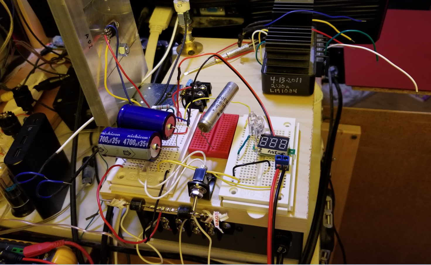
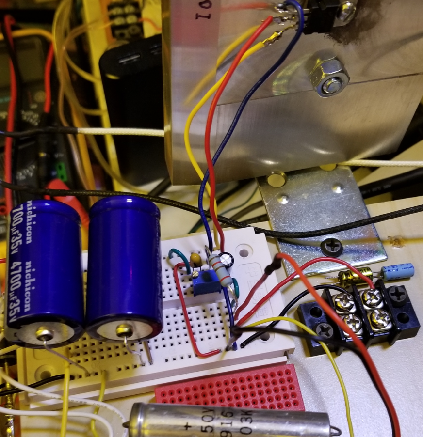
An accurate schematic would be more usefull in helping him than those photos. The hookup description is certainly inaccurate.
Dale Y
Re: LM 1084/338/317/etc... voltage drop at < 1A
sorry, my descriptions are all wrong. Just look at the photos.
everything works, it just doesn't work as well as I'd like and it doesnt work as spec.
I guess the real question is, do you see any issues with wiring, wires used; too long, too bent, to far etc...
everything works, it just doesn't work as well as I'd like and it doesnt work as spec.
I guess the real question is, do you see any issues with wiring, wires used; too long, too bent, to far etc...
-
dyarker
- Posts: 1923
- Joined: Fri Aug 22, 2003 1:01 am
- Location: Izmir, Turkiye; from Rochester, NY
- Contact:
Re: LM 1084/338/317/etc... voltage drop at < 1A
Still something wrong. Output of regulator should not vary (maybe 1/4V) from no load to full load.
Dale Y
-
Robert Reed
- Posts: 2277
- Joined: Wed Nov 24, 2004 1:01 am
- Location: ASHTABULA,OHIO
- Contact:
Re: LM 1084/338/317/etc... voltage drop at < 1A
Try a 0.33 MLC cap from regulator input terminal to ground. Do this right at the chips pin connection. Data sheets suggest any lead over 6" should be bypassed here. You are just about borderline so this may or may not be the problem. These chips are pretty fast and can oscillate without proper bypassing. If it does it may be at VHF frequencies you cannot see with a narrowband scope . All you would see are the ugly results.
Re: LM 1084/338/317/etc... voltage drop at < 1A
do you have an oscilloscope. it would be useful to see how much ripple there is at the input and output nodes. Usually bigger is better WRT the filter cap size, you can go a lot larger if you have the parts. We use 33,000uF (soda cans), Certainly a resistive connection on any wire can drop voltage and ruin performance.
Re: LM 1084/338/317/etc... voltage drop at < 1A
I don't have a .33 MLC capacitor. I have a .1 tantalium cap at the input, but like you mentioned, its a little far, about 3-4 inches.
I have a really old and heavy oscilloscope, but its filled with animal waste. Can I use a speaker with a capacitor instead, so I can listen to it? Or do I need dog ears to hear it?
I have a really old and heavy oscilloscope, but its filled with animal waste. Can I use a speaker with a capacitor instead, so I can listen to it? Or do I need dog ears to hear it?
-
Robert Reed
- Posts: 2277
- Joined: Wed Nov 24, 2004 1:01 am
- Location: ASHTABULA,OHIO
- Contact:
Re: LM 1084/338/317/etc... voltage drop at < 1A
Well the 0.1 cap ought to be OK for that short of a wire length even though its mounted on the bread board and not the chip. No you will never hear VHF (30-300 MHz) on any speaker (5hz-40KHz) even if you had a trained bat. You either have a defective chip or not enough voltage headroom to its input. Place your DMM on the input and read the DC volts at that point . This should be at least 3 volts higher than the ripples valley to the desired chips output voltage. Most DMMs will measure lower AC frequency. If yours does, make sure you see 120 Hz at that point and not 60Hz, which would indicate that one of the rectifiers is not conducting. This would be especially degrading your voltage as it would be operating half wave. At full wave the best you could hope for would be about 15VDC which would give marginal operation at 12 VDC output.
Re: LM 1084/338/317/etc... voltage drop at < 1A
if no oscilloscope you can still measure ripple with a DMM. just observe the AC and DC voltages separately. you should have a large cap near the rectifier to filter but you probably need another smaller cap near the regulator to shunt higher frequency operating transients to ground (which might be blocked by the inductance of a long wire trying to get back to the filter cap). I've never had trouble with these regulators, must be something fundamental, you already said your transformer was more than large enough.
Are you observing the maximum voltage drop spec, you can only regulate so far from the input voltage
try plotting output voltage vs output current on a graph, it might reveal a clue about the load impedance
Are you observing the maximum voltage drop spec, you can only regulate so far from the input voltage
try plotting output voltage vs output current on a graph, it might reveal a clue about the load impedance
Who is online
Users browsing this forum: No registered users and 7 guests