so, I' trying to power starve this motor I'm using[by using a resistance ladder with switches], it's a 12v DC motor rated at 500mA.
If I were to do this should I be using a particular wattage resistor? any recommended values?
I'm thinking just multiples of 5ohms should work [5,10,15,20,25...] but I'm a little rusty in this area.
and since it's only 500mA it should be fine but.... i'm uncertain and thought someone here might know...geh, maybe i'll just breadboard it and see...
ideas anyone?
thnx
[Moderators Note: Changed 1/2w to 1/4w as per posters request.]
use of 1/4w resistors to control a dc motor

Re: use of 1/4w resistors to control a dc motor
Hi there,
The power requirement for the resistors depends partly on what value they are and how
long they remain connected in the circuit. You are right in that a little experimentation
would help to determine what is best to use, value wise. However, often times a
1/2 watt resistor would be used instead of a 1/4 watt resistor for its ability to handle
physical shock and possible stress on the leads. In other words, a 1/2 watt resistor
is physically more rugged than a 1/4 watter so many times a 1/2 watter is used instead
just to make sure it doesnt break apart or some other physical shock doesnt easily
destroy it.
Just to note, power is computed from current with the formula:
P=I*I*R
where
P is the power in watts
I is the current in amperes
R is the resistance in ohms
Of course this is the average power calculation, so you may get by with more power
for a given resistor if it doesnt remain connected in the circuit for very long.
LEDs vs Bulbs, LEDs are winning.

Re: use of 1/4w resistors to control a dc motor
A 12Volt 0.5 Ampere motor calculates to a nominal resistance of 24 Ohms.
Adding a 6 Ohm resistor in series, totals 30 Ohm; which at 12 V the current is 0.4 A
P= IIR = 1 Watt for the 6 Ohm resistor
Adding a 12 Ohm resistor in series, totals 36 Ohm; which at 12 V the current is 0.33 A
P=IIR = 1.3 Watt
Adding a 24 Ohm resistor in series, totals 48 Ohms; Which at 12 V the current is 0.25 A
P=IIR = 1.5 Watt
Adding a 48 Ohm resistor in series, totals 72 Ohms; which at 12 V the current is 0.17 A
P=IIR = 1.33 Watt
Adding a 100 Ohm resistor in series, totals 124 Ohms; which at 12 V the current is 0.096 A
P=IIR = 0.9 Watt
Adding a 500 Ohm resistor in series, totals 524 Ohms; which at 12 V the current is 0.022 A
P=IIR = 0.26 Watt
Then, if you want to use 1/4 W resistors, the resistor must be greater than 500 Ohm.
Miguel
- Abolish the deciBel ! -

Re: use of 1/4w resistors to control a dc motor
Cant, are you sure the maximum current is only 500mA ? How big is it? Do you have an inerternet catalog link to it or a similar motor?cant wrote:so, I' trying to power starve this motor I'm using[by using a resistance ladder with switches], it's a 12v DC motor rated at 500mA.
A typical high end RC car motor won't even turn unless you feed it ~600ma, and it will suck >10A when mechanically loaded. So, I'm wondering if that 500mA specification is idle current or maximum load current?
Bob
-=VA7KOR=- My solar system includes Pluto.

Re: use of 1/4w resistors to control a dc motor
5 ohm/12V > 1/4W. at least make the first resistor 1/2W...
I'll point out the obvious that this is a pretty poor way to control a motor.
The better way is to use PWM. I'd use a microcontroller but it could be done with a 555 timer (though not as nice).
I'll point out the obvious that this is a pretty poor way to control a motor.
The better way is to use PWM. I'd use a microcontroller but it could be done with a 555 timer (though not as nice).
Re: use of 1/4w resistors to control a dc motor
philba: I realize this isn't a very efficient application here but its mostly due to me trying to work with what i have and keep this low-budget[as in $0]. Ideally i would you a micro-controller et.al but alas i am broke.
mrAL and Externet, thank you for your help in pointing me in the right direction as far as calculating values go.
Bob Scott: i couldnt find any other values for the motor other than the max rpms,
this morning's experimentations so far look promising...
and again, thanks everyone, i'm sure i'll eventually be back here with more questions
Re: use of 1/4w resistors to control a dc motor
Have you considered the use of a pot since PWM and such are out? For example Placing This Pot in series with your motor would give you a controlled voltage range of about 6 to 12 volts. Not sure where you are going with this as in increase voltage till the motor rotates or decrease voltage till the motor stalls (both unloaded on the motor). The pot cost about $4.00. The advantage is linear voltage change. A 50 Ohm pot would get you down to about 3 volts on the low end. I only used the 25 Ohm pot as an example as it is available at any Radio Shack for about four bucks.
Ron
Ron
Re: use of 1/4w resistors to control a dc motor
ah yes, good suggestion. I just need to take some time and go by ratshack to pick up some other supplies as well.
i'd probably use several as overall tuning pots since i was attempting to have several momentary-on switches to use to control it. already burnt out two pots earlier today
i'd probably use several as overall tuning pots since i was attempting to have several momentary-on switches to use to control it. already burnt out two pots earlier today
Re: use of 1/4w resistors to control a dc motor
The pot I suggested rated at 3 watts should handle it. It was just a cheap thought.
Ron
Ron
Re: use of 1/4w resistors to control a dc motor
OK, NOW I miss having Radio Shacks in Canada. A ~20 Ohm 3W pots used to be used for making cheap low power speaker faders, or tweeter brilliance controls. They are hard to find outside of RadShack.reloadron wrote:The pot I suggested rated at 3 watts should handle it. It was just a cheap thought.
Ron
Sorry, off topic.
I was wondering what the wattage rating of that wirewound pot would be if only turned up, say, 1/3 of its resistance value when used as a rheostat in series with a motor. I bet more than 1 watt but less than 3.
-=VA7KOR=- My solar system includes Pluto.
Re: use of 1/4w resistors to control a dc motor
My guess is that if the circuit were laid out like this:
the resulting voltage drops accross the pot and resulting circuit currents would look like this:
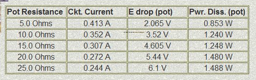
Likely a better choice in a pot would be maybe a 100 Ohm 5 Watt pot which is offered by Jameco and that pot can be found HERE. My initial thoughts were a little PWM circuit but as to quick and dirty a pot should work. The downside of the suggested pot as can be seen it will only get the motor voltage down to about 6 Volts or 1/2 its rated voltage. The upside is it can be had quickly and cheap at any Radio Shack. Now if the buyer lives close to any supply house then other parts would obviously work out better.
Something not considered in any of this that was mentioned is we assume no load on the motor and we don't know exactly what the 500 mA is all about. Would that be .5 A under a rated load for the motor? There is no mention of locked rotor either.
Ron
the resulting voltage drops accross the pot and resulting circuit currents would look like this:
Likely a better choice in a pot would be maybe a 100 Ohm 5 Watt pot which is offered by Jameco and that pot can be found HERE. My initial thoughts were a little PWM circuit but as to quick and dirty a pot should work. The downside of the suggested pot as can be seen it will only get the motor voltage down to about 6 Volts or 1/2 its rated voltage. The upside is it can be had quickly and cheap at any Radio Shack. Now if the buyer lives close to any supply house then other parts would obviously work out better.
Something not considered in any of this that was mentioned is we assume no load on the motor and we don't know exactly what the 500 mA is all about. Would that be .5 A under a rated load for the motor? There is no mention of locked rotor either.
Ron
Re: use of 1/4w resistors to control a dc motor
cant -cant wrote: Bob Scott: i couldnt find any other values for the motor other than the max rpms,
One thing you should try to do is find out how much juice the motor uses at stall or near stall conditions.
A quick and dirty way to do this is with a home made pony brake (the motor is small so this will work).
The idea is to grab the motor shaft with a couple of pieces of wood while the motor body is tied/clamped
to the work table. Insert a VOM set to amps in one of the motor's power leads. Turn the motor on (at 12 volts)
and squeeze the shaft with the wood pieces until it stops - or almost stops; note the meter reading and
turn off the motor (it's going to get hot doing this). Loading the shaft down until it stops is call it's stall
condition and the current at that point is called it's stall current. If the 500mA rating doesn't have stall
current associated with it, then more then likely, that's it's no-load or free-running current draw. For long
term continuos running in a project, keep the running current at 1/2 or less of the stall current - most motors
are most efficient in the range of 1/3 to 1/2 of their stall current, but, less current is always good as less current
produces less heat; less heat means longer life.
reloadron -
I love your schematic - clear and concise. What program/application did you use and how did you get that
drawing into this forum?
Phil Potter.
The world is - oh my gosh - round!!!
Re: use of 1/4w resistors to control a dc motor
chribec2 ask:
There are several ways to place an image in a post but that is how I generally do it.
As to the original p[ost I don't know what ever happened?
Ron
The drawing was done in a home version (Demo Version) or Orcad Unison Suite that I use. It is free but limits the user to I think 60 parts. Once I have a drawing I use a select all to copy and past it into a paint program, generally convert to a .gif file and place it on some webspace I have. That done I use the IMG tags and link to the webspace.reloadron -
I love your schematic - clear and concise. What program/application did you use and how did you get that
drawing into this forum?
There are several ways to place an image in a post but that is how I generally do it.
As to the original p[ost I don't know what ever happened?
Ron
Re: use of 1/4w resistors to control a dc motor
this is what came of it
http://www.youtube.com/watch?v=qhWNGoM855Y
http://www.youtube.com/watch?v=qhWNGoM855Y
Re: use of 1/4w resistors to control a dc motor
Some attention should be paid to power ratings here.
When a motor is stalled, the stall current is simply the applied voltage divided by the armature resistance. Even small motors can have stall currents in the ampere range. Either the motor controller has to be able to withstand the maximum stall current, or the motor controller has to limit the the current to a value that it can withstand.
The current drawn by a motor depends on its speed and loading. It may not act like a simple resistor, where the current is proportional to the applied voltage. When the motor is starting, it will draw the stall current until it begins moving, when the current will decrease.
If the motor is assumed to act like a resistor, then a 12 volt, 500 milliamp motor would act like a 24 ohm resistor. When the motor voltage is controlled by a series resistor, then the maximum dissipation in that resistor occurs when half of the applied voltage is across the resistor and the other half is across the motor. In this case, the resistor would have to dissipate 1.5 watts (6 volts at 250 milliamp). At this point the resistor would have a resistance of 24 ohms.
The power rating on a potentiometer or rheostat assumes that current is flowing through the entire resistance element. If only a fraction of the element is used, the allowable power dissipation is reduced. This can be interpreted as a maximum current rating for the resistance element. In the case of a 100 ohm, 5 watt pot, the current should not exceed 223 milliamps.
Current = SQRT(Power/Resistance)
Variable resistors intended for this type of use, such as the old Ohmite rheostats, were given a maximim current rating as well as a power rating.
The pot will tend to burn out at low resistance settings, since the current will be concentrated in a small part of the resistive element and will be at its maximum value due to the low total resistance in the circuit.
If the motor limits the current to 500 milliamps when the pot is at minimum, then a 100 ohm pot should be rated at 25 watts or more.
On small, low resistance pots, the wiper contact may not be capable of carrying as much current as the resistance element.
Who is online
Users browsing this forum: Bing [Bot] and 5 guests