Page 1 of 5
IS THERE WAY TO CHECK INFRA RED LED IN REMOTE TV IS GOOD OR
Posted: Thu Oct 19, 2006 7:26 pm
by electronics_field
IS THERE WAY TO CHECK INFRA RED LED IN REMOTE TV IS GOOD OR BROKEN BY ANALOG METER
AND THE INFRA RED LED TESTED TAKE OF FROM REMOTE OR INSIDE
Posted: Thu Oct 19, 2006 7:50 pm
by MicroRem
RS used to sell a strip of material that glowed when in the presence of IR. Not sure if they still sell it but it was cheap.
Tom
Posted: Thu Oct 19, 2006 7:55 pm
by ku7485
Perhaps you can build a infrared detector circuit to detect if there is an infrared signal.
If you want, I can draw-up a schematic and send it you. Just PM me for it. The circuit is easy to build, basically you need a photo transistor, an LED (to display status whether the remote control is working or not), and a resistor (to control current).

Posted: Thu Oct 19, 2006 8:41 pm
by electronics_field
THANKS SIR SEND ME THE CIRCUIT
Posted: Thu Oct 19, 2006 9:08 pm
by Chris Smith
I use the IR scope or the Starlight scope, but RS used to sell a strip that converted the signal to a almost visable signal so you could tell.
That or any IR reciever transistor and a op-amp circuit will show the signal.
Posted: Thu Oct 19, 2006 9:37 pm
by philba
You guys make me laugh. just get any digital camera and look at the IR LED through it. or a camcorder. or a cam phone.
Posted: Thu Oct 19, 2006 9:51 pm
by Chris Smith
Were soo rich, lets just buy a camera?
Posted: Thu Oct 19, 2006 11:21 pm
by MrAl
Hi again,
Ku, how about posting the circuit here somehow so we can all
take a look at it?
Thanks...
Posted: Fri Oct 20, 2006 5:43 am
by ku7485
A cheap alternative to the proposed suggestions would be my circuit:
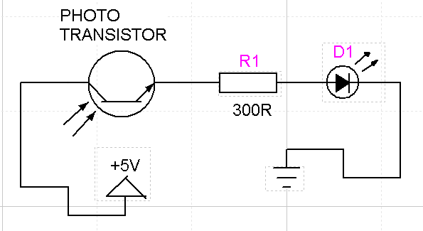
I drew this up as fast as I could this morning so I can share it with you guys. If you have any comments on my drawing, please tell me.
I hope this circuit helps.
Anyway, the circuit
uses a phototransistor, NOT a photodiode or a photoresistor. You can probably get a phototransistor at your local RadioShack. To use this circuit, just place your remote control next to the phototransistor and press some buttons. If the LED lights up that means it works. If it doesn't, then you need to either replace the IR LED or get a new remote.
Posted: Fri Oct 20, 2006 6:38 am
by dyarker
Just turn the LED around.
And the transistor

edited: The schematic has been edited so ignore this note now. Also see alternate schematic and discussion below.
Posted: Fri Oct 20, 2006 7:04 am
by ku7485
Can't believe I missed that. Must of been because I was in a hurry...
The power and ground should be switched.
Posted: Fri Oct 20, 2006 9:03 am
by electronics_field
thanks mate please can you put fuul circuit again
Posted: Fri Oct 20, 2006 10:09 am
by HighFrequency
The circuit is there... just switch power and ground
Posted: Fri Oct 20, 2006 10:33 am
by haklesup
The IR sensor strip was RS# 276-1099 but naturally they don't sell it anymore but they do sell the phototransistor #276-145.
WRT the suggested circuit (ignoring the reversal since it is already resolved). You may find it easier to power it with a 9V battery in which case change the resistor to about 540 or if you want to use 2 AA batteries and 3V then 180 ohms will give the equivelent current to the LED as the original circuit which is at most 16mA (I ignored the impedance of the detector in my rough calc). There is some wiggle room for variation on the resistor values, just don't go so low (R) so that the current burns out the LED or phototransistor or so high you can't see the LED glow.
Such a detector might be sensitive to other near-IR sources like sunlight but it should work fine indoors.
Posted: Fri Oct 20, 2006 11:50 am
by philba
Chris Smith wrote:Were soo rich, lets just buy a camera?
I suppose there are some people that don't have some sort of digital camera (or cam corder or web cam). though i bet it's a small percentage these days.
On that circuit. I think you want the Phototransistor source (edit, er make that emitter) going to ground - it's an NPN with the light causing bias current. But it's going to be very dependent on the PT you use.
Here's my take on the circuit:

R1 is for sensitivity adjust. 50K or higher, depending on the PT
R2 should be 1-2K though it's not that critical. lower is ok.
R3 should be to limit the LED current. 270 - 470 will work ok.
Q1 is any small signal PNP.
You can use any PT - an IR one is better but almost anything will do in a pinch. The advantage of this circuit is that lighting the LED is seperate from the phototransistor current.
The PT conducts in the presence of light and pulls Q1 base low, causing it to conduct and supply current to the LED. The sensitivity adjust allows you to compensate for ambient light.
You can use a different supply voltage - 3 to 9 but change R3 via the formula R = (V-2)*100
adjust R1 to the point where the LED goes off and it should light up when hit with IR.
disclaimer: I haven't built this...
edit: ugh. NPN transistors have emitters, not sources. I've got FETs on the brain. sorry