Page 1 of 1
SIGNAL TRACER
Posted: Tue Oct 13, 2009 9:05 am
by numb3rs
I am looking to make a signal tracer. I have a stand alone amp that it can be plugged into. Does anyone have a schematic of one they built that has preformed well for them.
Thanks
Re: SIGNAL TRACER
Posted: Tue Oct 13, 2009 11:07 am
by CeaSaR
What kind of tracer do you want? One for tracing through audio amps to troubleshoot them or
one to inject a signal over AC mains to follow wires through the house? They are 2 different
beasts entirely.
CeaSaR
Re: SIGNAL TRACER
Posted: Tue Oct 13, 2009 11:15 am
by numb3rs
One for tracing through audio amps to troubleshoot them.
Thank you for the reply and help!
Re: SIGNAL TRACER
Posted: Tue Oct 13, 2009 12:57 pm
by reloadron
This Page Link shows some early signal tracers. I actually have the old Knight Kit (Allied Radio) and if you scroll down the page you will see some schematics for the probes that were used. Really pretty simple to construct as I replaced mine many years ago. A few resistors, a cap and a germanium diode should get you going. I doubt you will find a 1N34 but there must be others. I drilled out a plexiglass dowel and threaded a tip into it. The components all fit into the dowel. Hope the link helps...
Ron
Re: SIGNAL TRACER
Posted: Wed Oct 14, 2009 9:02 am
by sghioto
numb3rs,
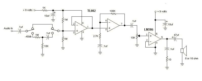
If it's just for audio all you really need is a high impedance "utility" amplifier. Here's a schematic for one I have used for years. Total voltage gain is just under 1000 with an input impedance of 500K to 1M depending on the attenuator switch position. Runs off a 9 volt battery.
Steve G
Re: SIGNAL TRACER
Posted: Sat Nov 28, 2009 8:09 pm
by CeaSaR
numb3rs,
If you are still looking for an inexpensive tracer, I found one in my 1996 Electronic Experimenter's Handbook.
It uses 2 BC109C NPN transistors and a small handfull of caps and resistors. Let me know and I'll upload it
for you.
CeaSaR
Re: SIGNAL TRACER
Posted: Sat Nov 28, 2009 8:29 pm
by Dean Huster
Seems to me that (especially when directly connected without the attenuator) that the chargine of that input coupling (blocking) capacitor when connecting to the plate circuit of a tube amp has the propensity of developing a spike that could destroy the input of the first op amp if it can't handle such voltages. That's one reason why Tektronix scopes, when you have the input coupling switch set to GND, allows you to precharge the scope's input coupling cap when connecting to high DC voltages when you're set to 5mv/DIV on the attenuator.
Dean
Re: SIGNAL TRACER
Posted: Mon Nov 30, 2009 2:21 pm
by sofaspud
The OP stated "I have a stand alone amp that it can be plugged into" not realizing that he already had the audio signal tracer
being requested. All that's needed is the probes. Probably the easiest thing to do is replace the amp's input jack(s) with banana
jacks and use regular ol' DVM probes. An alligator clip for the ground connection and an in-line DC blocking capacitor on the
positive lead are helpful additions. And emphasizing Dean's cautions, care should be used when troubleshooting, or you'll have
two amps in need of repair.

Re: SIGNAL TRACER
Posted: Mon Nov 30, 2009 2:59 pm
by reloadron
The link I provided in my post has schematics of basic signal tracer probes at the bottom of the page. The schematics use the old 1N34 germanium diode which can be substituted.
Ron