i been racking my brain on a battery voltage monitor, cannot get things to work right.
i am wanting to use a bi-polar 2 lead led ( NOT bi-color 3-lead ) as the indicator, because i have a ton of them, i want to put to use..
the circuit will need to have a hystress of some sort.
and i need to be able to set the upper and lower voltage set points.
the bonus part would to be able to flash the red section of the led if a overvoltage was to happen. this is where i am getting stumped.
i had planned to try to use either a LM324 or LM358
seen this circuit, planned to try to modify it for bi-polar use..
http://kd1jv.qrpradio.com/batmon/batmon.HTM
but how to incorperate the flashing overvoltage use.
anyone able to help out ?
if bi-polar led is not possible, then how bout one with the bi-color led
thanx
battery voltage monitor - help
Re: battery voltage monitor - help
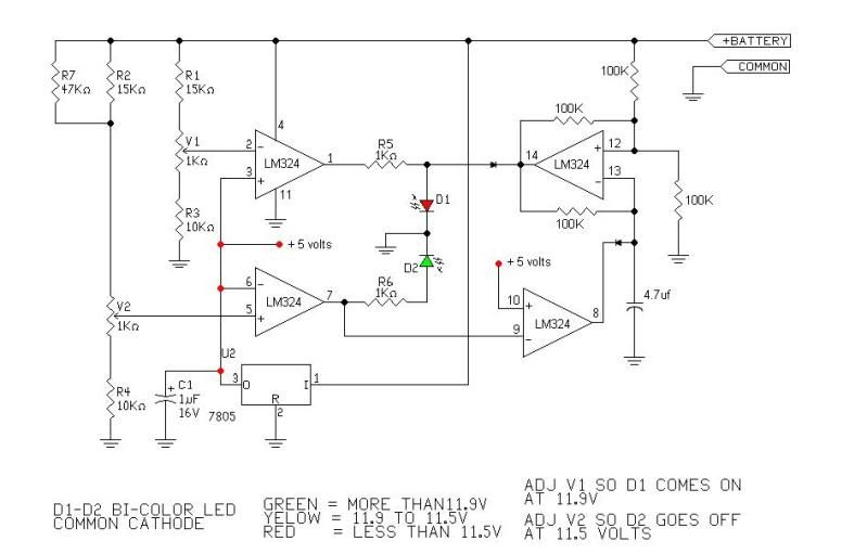
Here's a modified version using the LM324 and the same 3 leg dual color LED.
It maintains the same three color scheme to indicate battery voltage but the red LED will blink when the voltage drops to 11.5 volts.
Steve G.
And a version using a bi-polar LED.
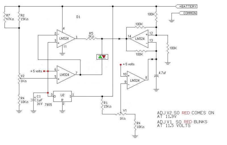
It maintains the same three color scheme to indicate battery voltage but the red LED will blink when the voltage drops to 11.5 volts.
Steve G.
And a version using a bi-polar LED.

Re: battery voltage monitor - help
Hi dac,
What happened to the last version we were talking about in the other thread?
BTW a voltage reference diode works better than a 7805 for these kinds of applications as it is much more temperature stable.
What happened to the last version we were talking about in the other thread?
BTW a voltage reference diode works better than a 7805 for these kinds of applications as it is much more temperature stable.
LEDs vs Bulbs, LEDs are winning.
-
dacflyer

- Posts: 4748
- Joined: Fri Feb 08, 2002 1:01 am
- Location: USA / North Carolina / Fayetteville
- Contact:
Re: battery voltage monitor - help
sghioto >> i was looking for the red to blink when the voltage got too high,,,
MrAl >> i was studying it, it could work, but i was wanting to add the bonus of making the red led blink in a over voltage mode. and couldn't figure out how to add it into the circuit.
i have not settled on any one yet..

gotta find me some ref. diodes also
MrAl >> i was studying it, it could work, but i was wanting to add the bonus of making the red led blink in a over voltage mode. and couldn't figure out how to add it into the circuit.
i have not settled on any one yet..
gotta find me some ref. diodes also
Re: battery voltage monitor - help
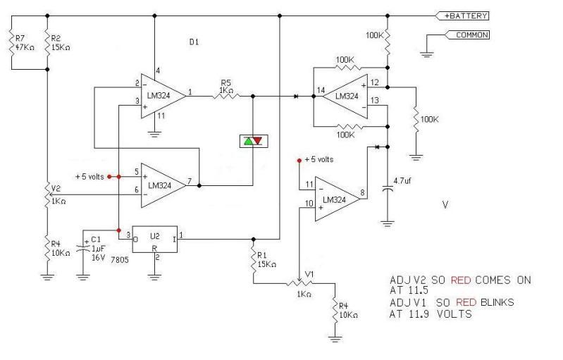
OK. Here's a third version with the red LED indicating the higher voltage. Remember the component values are based on a 12 volt battery in the example circuit.i was looking for the red to blink when the voltage got too high
Steve G.

Re: battery voltage monitor - help
Why not just use a blinking red LED for the HIGH voltage indicator?
http://www.radioshack.com/product/index ... Id=2062553
http://www.radioshack.com/product/index ... Id=2062553
WA2RBA
-
dacflyer
- Posts: 4748
- Joined: Fri Feb 08, 2002 1:01 am
- Location: USA / North Carolina / Fayetteville
- Contact:
Re: battery voltage monitor - help
beacuse i want a steady red for NOT charging , Green = charging and then
blinking red for over-voltage..
is there an adjustment for the green set point ?
blinking red for over-voltage..
is there an adjustment for the green set point ?
Re: battery voltage monitor - help
is there an adjustment for the green set point ?
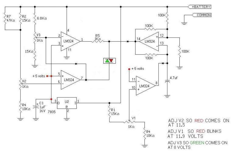
In the third version the green LED is on as soon as the battery voltage is above what the LM324 requires.
So here's version #4with a green set point at 8 volts.
Steve G.
-
dacflyer
- Posts: 4748
- Joined: Fri Feb 08, 2002 1:01 am
- Location: USA / North Carolina / Fayetteville
- Contact:
Re: battery voltage monitor - help
thanks sghioto, you been a big help.. not to be a pest, but the green is supposed to be the
"charging" indication.
can i adjust the V3 for a higher voltage ?
and the V1 , V2 for a different voltage or is the range limited ?
ex. red = low voltage 11 volts
green = charging 13 volts
blinking red = over voltage 14 volts
"charging" indication.
can i adjust the V3 for a higher voltage ?
and the V1 , V2 for a different voltage or is the range limited ?
ex. red = low voltage 11 volts
green = charging 13 volts
blinking red = over voltage 14 volts
Re: battery voltage monitor - help
Your welcome dacflyer
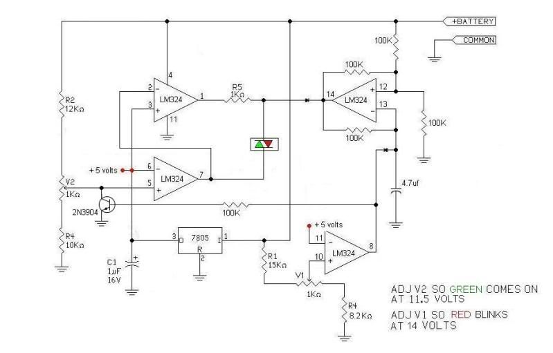
The range is limited to the DC values on the schematic but you can change the resistor values in the voltage dividers to meet your requirements. But if I understand your example correctly then a version #5 will be needed.
Steve G.
The range is limited to the DC values on the schematic but you can change the resistor values in the voltage dividers to meet your requirements. But if I understand your example correctly then a version #5 will be needed.
So let me see if I've got this straight. When the battery drops to 11 volts you want the red LED to come on telling you to connect the charger. As the battery charges back up the red LED will go off when the voltage goes above 11 volts but the green LED does not light until the battery reaches 13 volts. The green LED stays on until the voltage reaches 14 volts which causes the red LED to come back on and blink. Is this correct?ex. red = low voltage 11 volts
green = charging 13 volts
blinking red = over voltage 14 volts
Steve G.
-
dacflyer
- Posts: 4748
- Joined: Fri Feb 08, 2002 1:01 am
- Location: USA / North Carolina / Fayetteville
- Contact:
Re: battery voltage monitor - help
the unit will be used on my ultralight.
the leds should not be off any time except when turned off.
so the red is on at 11 volts and less...
the green is on at a range of 11.5 volts to 13.5 volts ( range is not critical )
and then the flashing red comes on if voltage goes above 14 volts..
my thing is,, i could do this with individual op amps and a few leds, but i am trying to do it with a single bi-polar led. and thats's where i am running into problems.
( 3-lead is possible, but the 2 lead is prefered because i have a lot of them on hand. )
Re: battery voltage monitor - help
Hi again dac,
Well gee, get the blink function from a 555 timer ic and gate it with the LED drive when needed. Shouldnt be too hard, however this application is starting to scream out for a microcontroller ic chip. One 2 dollar chip and one low power 5v regulator like the LM317L and you have yourself a circuit which will make your LEDs do whatever you want them to do, blink now, blink later, blink when the sun sets
You get the picture.
Lets see one pin for input to monitor the battery line, two pins to drive the 2 pin bi color LED (no other driver needed), sounds pretty simple. Two resistors for the LM317L to set the voltage (better than using the 78L05) or settle for the 78L05 if the temperature isnt expected to vary too much.
If you really do need to adjust, two more pins for pot inputs to adjust the high and low voltages.
With a 6 i/o pin device that leaves one digital input pin unused, so yes a $2 chip could do it.
Two more resistors to scale down the battery voltage for the uC chip input.
Total current draw can be kept very low, and even lower if you want to get into using the sleep mode to power down and wake up every 10 seconds to take measurements.
I'd say the program can be created in one afternoon.
Parts count:
12F something PIC chip with socket,
78L05 or LM317 with 2 set resistors,
2 input scaling resistors,
1 LED current limit resistor.
For adjustments:
10k pots (2) regular version, or 50k pots for lower power version.
PC board with holes for DIP socket and other parts, plus some #24 or #22 wire.
Actually now that i think about it i may be able to use something like this myself too. I have been using 12v lead acid batteries to run my cordless drill (after replacing batteries one time which cost $40 dollars and they went dead 5 years later). So i may be able to use something like this, low power, to keep connected to my (now dedicated to the drill) 12v lead acid battery. I'd like to make sure it stays in condition for quick usage when the drill is needed.
If the above sounds interesting i'll start looking into making some of these. I guess i could open source the program code so you can make more of your own chips too if you ever get so inclined to do so. If you sell any though i want royalties
LEDs vs Bulbs, LEDs are winning.
-
dacflyer
- Posts: 4748
- Joined: Fri Feb 08, 2002 1:01 am
- Location: USA / North Carolina / Fayetteville
- Contact:
Re: battery voltage monitor - help
lol.. i cannot keep batterys in my drills either, i rebuilt battery packs 7.2 volt.
they go bad already in less than a year. i still like my old drills, because they are powerful enough to drive in 3 inch deck screws, and the drill is light also, not heavy or bulky like the newer 12, 18 & 24 volt drills..
anyway, i did not opt for micro controller, because i cannot for the life of me do programming.
i can program a chip , no problem, but i cannot make the program, i do not have the ability.
wanted to take a micro class here at local tech collage. but they do not have any evening or weekend classes. and i need hands on training, books are no help to me.
so thats why i was looking at the conventional method. and its something i am a little more familliar with...
there is a lot of stuff i wanna do with micro controllers, but i am stuck if i am not program smart..
i have some small displays i wanted to play with. a member here was helping me for a while, but then he dissapeard..i think hes out of country again for a while..
they go bad already in less than a year. i still like my old drills, because they are powerful enough to drive in 3 inch deck screws, and the drill is light also, not heavy or bulky like the newer 12, 18 & 24 volt drills..
anyway, i did not opt for micro controller, because i cannot for the life of me do programming.
i can program a chip , no problem, but i cannot make the program, i do not have the ability.
wanted to take a micro class here at local tech collage. but they do not have any evening or weekend classes.
so thats why i was looking at the conventional method. and its something i am a little more familliar with...
there is a lot of stuff i wanna do with micro controllers, but i am stuck if i am not program smart..
i have some small displays i wanted to play with. a member here was helping me for a while, but then he dissapeard..i think hes out of country again for a while..
Re: battery voltage monitor - help
"this application is starting to scream out for a microcontroller ic chip"
I couldn't agree more MrAl, but we've been down this road before with dac and micros so here's version #5
Steve G.
I couldn't agree more MrAl, but we've been down this road before with dac and micros
Steve G.
-
dacflyer
- Posts: 4748
- Joined: Fri Feb 08, 2002 1:01 am
- Location: USA / North Carolina / Fayetteville
- Contact:
Re: battery voltage monitor - help
thanks again i will let you know the results this weekend...
Who is online
Users browsing this forum: Google [Bot] and 19 guests