
YES- you can use the standard BS1 SIP style chip from Parallax as a drop-in replacement.The BS1-OEM kit is no longer available from Parallax. Can I use the standard BS1-IC chip they do stock?
YES- you will need to add your own BS1 Programming header. This is fairly simple to do. You need only add a 3-pin .100 spacing header to the board as shown here:Do I need to make any changes to use the BS1-IC instead of the BS1-OEM?
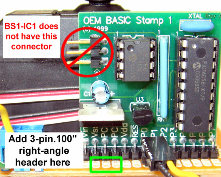
Electronic Goldmine has a nice selectionWhere can I get the .100" spacing headers?
The BS1 code I've written for the Peanut Butter Monster Detector will not run directly on a BSII without modification. As there is a drop-in replacement for the BS1-OEM board, converting the code should not be necessary.Parallax does sell an OEM Basic Stamp 2, would this work with your code and schematic?
Sure- I prepared a typical high-brightness LED by clipping one led very short and replacing that leg by soldering in a 330ohm resistor. I then "tinned" the two lamp connectors inside the push button. I then clipped the LED lead and the resistor lead to fit under the cap of the button. I then soldered it into place using forceps to hold the part while I soldered. Of course, you don't have to go to this much work.Can you share in more detail what you did to replace the lamp in the push button with the red LED? (i.e. how you connected it after removing the lamp and if a resistor is needed)
Sure! It was Peter Pan Peanut Butter! Lots of room in a jar that big.I've been to several local supermarkets and haven't found a peanut butter jar that matches what you used, all seem to have too small an opening to fit the PCB. Do you recall what brand peanut butter your jar was?
Yes- The source code is available in the FTP section of the Nuts and Volts website right hereI can't seem to find the "Complete Source Code" listed as being available on the Nuts and VOlts Website. Can you give me a link?
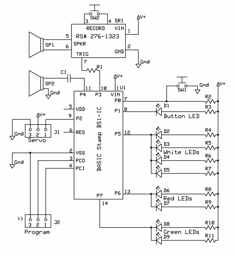
Any "back EMF" silicon diode should work. I used one from a bunch I got from AllElectronicsWhat size is the diode you added on the bottom of the board?
I used a surplus 6v wall wart I had laying around. I would recommend that you use a wall-wart with as close to 6 volts as you can find. NOTE: do NOT exceed 7.5v input voltage as the Servo Motor is limited to no more than 7.5volts! If you are unsure of the power supply you have, be safe and go with the 7.5v power supply sold by Parallax.And what is the voltage? 9V?
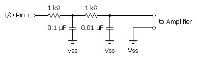
Wow. That's a new one on me!The Sound Module I purchased from radio shack does not have the resistors shown. How do I connect it?
Please let me know if you have any questions not addressed here. Also, please feel free to talk amongst yourselves and share ideas, concerns and questions. I'll keep an eye on this thread and help where I can!
Vern