lets see if i can explain this right for all to understand.....
i am working on a differnt sort of turn signal reminder.
it will consist or a 556 or 2- 555's
the 1st stage will get its power when you turn on the turn signal, theres typically solid power before it gets into the turnsignal flasher unit. and this will start a 10 second count down timer (no problem for me so far)
but the 1st stage timer will be inhibited while your foot is on the brake pedel. (12volts) the timer will not start to count down until your foot lets off the brake.
but i want to know how to inhibit the timer with +12volt.
basically / typically you turn on the turnsignal as you get to the light. this powers up the unit, and you usually do not take your foot off the brake while waiting to make your turn. this way while your waiting at a long light or stop sign the timer is not going off annoying the driver behind ya.
so after you make the turn. you have about 10 sec before your reminded with the buzzer. and if you press the brake again, it will reset the timer once again..
stage 2 of my timer will be the buzzer thats activated by the output of stage 1..
knowhatimean ?
stumped on a 555/556 project.

This is the same concept that was published in Popular Electronics a
number of years ago (mid '90's I think):
A 556 was set up with IC1a as a free running oscillator when power was
supplied to the board parallel and prior to the flasher. After 30 seconds,
the output would trigger IC1b and produce a sound, thereby reminding
the driver to cancel the turn signal. The reset pin was held low when the
brake was applied via a transistor inverter, preventing IC1a from
running. Additionally, I think there were steering diodes involved at the
input so as not to turn on both signals when in use.
A similar question was asked several months ago in Q&A, so if Russ
Kincaid is out there, please take note. I, unfortunately, have not been
able to find my copy of PE containing this article.
Hope this helps Dac.
CeaSaR
EDIT:
As Gene Wilder said in Charlie and the Chocolate Factory - Scratch that,
reverse it. IC1a should be a one-shot that triggers IC1b - astable
oscillator. I did say it was published a while ago.
Hey, what do I know?

If you can come up with a truth table and timing diagram then you will be a lot closer to having someone come up with a circuit. Sounds like you'll need a few logic gates and pullup resistors in addtion to the timers. A series cap and pullup R is a good way to convert a long pulse into a short one at the rising or falling edge.
-
dacflyer

- Posts: 4751
- Joined: Fri Feb 08, 2002 1:01 am
- Location: USA / North Carolina / Fayetteville
- Contact:
ceasar, i think i have that artical, but it is using the steering dioads tapped onto the turnsignal lights. the one i am looking to make seems to be a bit simpler, i had made a flashing 3rd brake light like this with just a 556 and a transister. the light flashes for a few seconds and then stays on.
and starts all over again when you reapply the brake.
i'll look at that canadian site to see something of use...thanks
and starts all over again when you reapply the brake.
i'll look at that canadian site to see something of use...thanks

Hi there,
I was thinking maybe a 555 connected to turn signal, then a
transistor 2N2222 to keep the timing capacitor of the 555 discharged
when the brake pedal is pushed down. This will reset the time
period and keep the output off for 10 seconds. The 555 is
rigged to go off in 10 seconds by the size of the resistors and
the timing cap. This would trigger a buzzer or just an LED.
LEDs vs Bulbs, LEDs are winning.

-
dacflyer
- Posts: 4751
- Joined: Fri Feb 08, 2002 1:01 am
- Location: USA / North Carolina / Fayetteville
- Contact:
Re: stumped on a 555/556 project.
ok, its been a while, but i been really busy and i finally have time to catch up on projects..
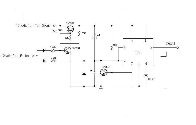
i finally got time to put this thing to gether as " sghioto " shows in the schematic.
problem is.. when 12v is applied to the 555 from the turnsignal 12v the timer starts and times out.
what i need is.. when 12v is applied from the turn signal, the timer will not start timing untill power from brake activates it.. ( wake up ? ). then when the brake is released, the timer will then start .... and can be reset again when brake is re-applied.. output will be active until turn signal is turned off.
right now if turn signal is turned on and no brake is ever applied the 555 will go active.
is there a simple soulution to this ?? Hmmm.
i have another idea for headlight reminder..when it times out,, horn will honk every few seconds.
might need help with as well
thanks..
Re: stumped on a 555/556 project.
dacflyer,
Geez that was over a year ago Well from your origional post you said your foot would normally be on the brake while waiting to make the turn. Hence the timer is inhibited or reset. So the circuit is doing exactly what you asked for. Unless your are stopped and the car is in neutral with no brake do I see an issue. I'll look at it again and see if I can make the changes.
Steve G.
Geez that was over a year ago
Steve G.

Re: stumped on a 555/556 project.
Then as the driver's hearing deteriorates with age, people will see the old geezer driving down the highway with blinker on and horn honking.dacflyer wrote:i have another idea for headlight reminder..when it times out,, horn will honk every few seconds.
might need help with as well
thanks..
It may not be legal in some states/provinces to activate the horn except in an emergency situation when you are on a public road. Years ago, the local auto parts chain used to sell replacement direction signal flashers with a built-in chime, but they became illegal too and became unavailable.
I used to buy repacement "solid state" flashers from the auto parts store. I don't know why they called them "solid state". The relay was still there. I bought them for their loud clicking noise to remind me the signal was on. Due to being electronic is some nature, unlike the originals they would still flash when either one front or rear signal bulb was burned out. Maybe they are still available from auto parts stores. They do click way louder than the stock flasher. That is why I bought them. Trouble is, you have to check your signal lights manually for burned out bulbs occasionally.
My present GM vehicles are built after 1995. In both of them, if I leave the direction signal on for more than 10 minutes or so, the vehicle OBDC computers turn on an reminder alarm that chimes with every flash. I did not see this feature is mentioned in the owners manuals.
I used to buy Sonalert alarm modules for use as headlight on reminders when the key is turned off. Just wire between the headlight switch and and an accessory load positive wire like a heater blower winding. Nowadays, headlights are automatic. I hardly ever manually turn them on except for in tunnels, and the cars have reminder chimes as standard equipment.
For my motorcycle, I wired a Sonalert to the turn signal switch to beep with every flash. (Motorcycles don't have an automatic disengagement of the turn signal.)
Bob
-=VA7KOR=- My solar system includes Pluto.
Re: stumped on a 555/556 project.
OK, here's the latest update after re-reading dacflyer's last post. Added the two transistor switch so there's no power to the 555 until the braked is pressed and a second transistor switch to activate after the 10 second timer has elapsed. Operation again is: Turn Signal on, no power to circuit until brake is pressed. After the brake is released the timer will start but will reset anytime the brake is applied before the 10 second timer runs out. After the timer runs out the brake pedal will no longer reset the circuit. Output from the 555 will stay high until the Turn Signal is off. Is that about it?
Steve G.
Steve G.
-
dacflyer
- Posts: 4751
- Joined: Fri Feb 08, 2002 1:01 am
- Location: USA / North Carolina / Fayetteville
- Contact:
Re: stumped on a 555/556 project.
yes , thanks..
you know how it is when other choirs take presidence over hobby time
NOTE >>> i just got the OK from local power co. that i can now grid tie,, so i'll be working on this also.. red tape is horrible tho...35 copies of this and that with NOTICE ! what ever that is
i am shopping for a grid tie inverter now also.. looks like i'll be going with a sunnyboy 3000US
-
dacflyer
- Posts: 4751
- Joined: Fri Feb 08, 2002 1:01 am
- Location: USA / North Carolina / Fayetteville
- Contact:
Re: stumped on a 555/556 project.
well i am officially bummed out.
after all this time i finally had time to complete this project in my spare time.
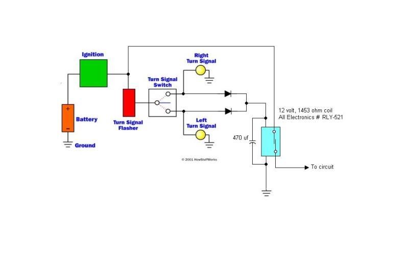
it bench test just great. BUT to my dismay it will not work on my car, due to the fact that the turn signal flasher modual has power on it all the time, but it does not flash until there is a load on it.. its a 3 prong modual . 12 goes in it, the output goes to the turn signal sw. and the 3rd terminal is ground.. when the turn signal switch is flipped it just connects the load, the electronics in the modual do the work.. it has in it, just the usual coil and a cap. never understood how it worked, but it does,.
now if it was the 2 terminal type or thermal flasher. then it would have worked..because the 12 volts is switched on when you flip the switch to turn left or right.
anyone have a suggestion that might work?
after all this time i finally had time to complete this project in my spare time.
it bench test just great. BUT
now if it was the 2 terminal type or thermal flasher. then it would have worked..because the 12 volts is switched on when you flip the switch to turn left or right.
anyone have a suggestion that might work?
Re: stumped on a 555/556 project.
Ron,
This should work with the right value cap and coil.
Steve G.
This should work with the right value cap and coil.
Steve G.
Who is online
Users browsing this forum: No registered users and 150 guests