Getting started wire wrapping (or prototyping like this)

This is the place for any magazine-related discussions that don't fit in any of the column discussion boards below.
Post Reply
User avatar
GoingFastTurningLeft
Posts: 163
Joined: Wed Sep 06, 2006 7:33 pm
Contact:

Getting started wire wrapping (or prototyping like this)

Post by GoingFastTurningLeft »

I want to start making prototype PCB's like I see online and in N&V. Just like the pictures down below. This looks like they're wire wrapped and then soldered?

I'm putting in a parts order from Digi-key later today. Any recommendations to what to get to get started wire wrap prototyping? To I need any additional parts when I'm going to be doing it like this?

Image


Image
User avatar
Dave Dixon
Posts: 436
Joined: Thu May 01, 2003 1:01 am
Location: Wichita, KS
Contact:

Post by Dave Dixon »

Those photos do not look like wire wrap to me. DigiKey has several tools for doing it. One is a couple of hundred dollars (V1081-ND)! I've never done it myself, but have worked on boards that other people have done. Obviously you don't want to do any high frequency stuff, but it seems to be a practical way to prototype.
Wikipedia dot org has a very good write-up with some cool photos. I just learned that the Apollo Guidance Computer used that technique! How cool is that? Hope this shed just a little light on the subject. Check this:
http://en.wikipedia.org/wiki/Wire_wrap
Dave
User avatar
GoingFastTurningLeft
Posts: 163
Joined: Wed Sep 06, 2006 7:33 pm
Contact:

Post by GoingFastTurningLeft »

I was under the impression that's wire wrap wire.

Maybe they just use the wire and don't use the tool?

Hopefully somebody on here who's done boards like these will see this and tell me what the heck they're doing.

I could have sworn it was wire wrapping.
User avatar
philba
Posts: 2050
Joined: Tue Nov 30, 2004 1:01 am
Location: Seattle
Contact:

Post by philba »

definitely NOT wirewrap. This is wirewrap.
Image
note the absence of solder. Your photos look like simple point to point soldering.

Wirewrap techniques have definitely gone the way of the vacuum tube - some use but not very much.

The technique used on your boards is simple. Cut a piece of wire to length + a little bit. Strip insulation, twist one end around the target lead, solder it and then do the same for the other target lead. Nothing magic.
User avatar
jwax
Posts: 2234
Joined: Mon Feb 09, 2004 1:01 am
Location: NY
Contact:

Post by jwax »

I recall an enamel-covered wire that when wrapped tight around the dedicated square pin, would pierce the insulation reliably. Or so they said.
Built a test box using it ages ago, but was always troubled by intermittents. Ended up soldering all the joints.
Robert Reed
Posts: 2277
Joined: Wed Nov 24, 2004 1:01 am
Location: ASHTABULA,OHIO
Contact:

Post by Robert Reed »

Why wouild you even want to use wire wrap? It was popular 40 years ago for LARGE scale circuits with many tie points. Used mostly in production for speed and economy. When done with the right tools (expensive) and in the right hands it worked well. Strictly for low speed digital only. Can cause a world of problems with RF, high speed timing and analog low level circuits. Also very easy to break wires and botch up connections, takes good tools and experience to get it right ALL of the time. If your like most of us building circuits with less than a few hundred connect points, solder is the way to go - neater, cleaner and more hi frequency friendly. BTW in looking at the circ. bd. pix, there are perfboards out there that have the triple foil pattern such as that, but with two bus traces running between them for ground and Vcc. these end up running directly under the DIP ICs. It is about the only good product that Radio Shack still sells.
Bigglez
Posts: 1282
Joined: Mon Oct 15, 2007 7:39 pm
Contact:

Post by Bigglez »

Greetings David H.,
GoingFastTurningLeft wrote:I was under the impression that's wire wrap wire.

Maybe they just use the wire and don't use the tool?

Hopefully somebody on here who's done boards like these will see this and tell me what the heck they're doing.

I could have sworn it was wire wrapping.
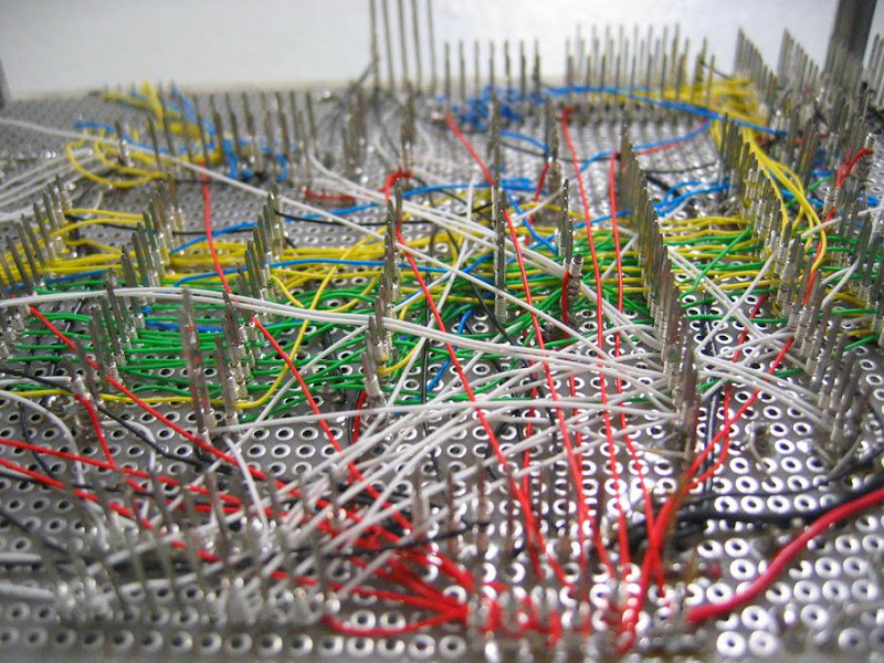
As others have said the wire-wrap technique is history.
However, the wire specially designed for wire-wrap is
ideal for point-to-point solder connections on proto
boards, and fixing PCBs errors during development.

There are etched PCBs with three-hole pads and bus
traces (power and ground) and also open field proto
boards with a grid of pads. Some versions have a
ground plane on one side which is very helpful in
most designs with high speed logic. The better
quality proto boards have PTH (Plated Through Holes)
that makes attaching parts much easier.

The wire-wrap wire is thin and flexible, but too thin for
power and ground connections. I use a combination
of tinned copper wire (20AWG) for power and wire-wrap
for point to point connections. For long runs of tinned
copper I place PTFE sleeving over the bare wires,
and shape the links to clear the pads and other
components.

I only solder the wire ends, not wrap or attach them.
(On protos the wiring is often redone a few times).

Also, for quick turns I don't bend the wire-wrap
connections neatly. After every wire is attached I
crunch the wrier-wrap ratsnest flat.

Here's a few PIX from two projects sitting on my bench:

Image
Image
Image
Image
Image

Comments Welcome!
User avatar
evahle
Posts: 188
Joined: Mon Aug 13, 2007 3:48 am
Contact:

Breadboard

Post by evahle »

Nice pictures Bigglez. David H.? That was funny! LOL. :grin:

Anyway, Hi TurningLeft! My favorite way to experiment and build electronics hasn't changed in 25 years. It is still a favorite among most hobbyists.

In the picture you can see to the left is a breadboard that you can get on Ebay for about $5 each. I have two connected together in the picture. To the right lower, I have a PCB that almost exactly matches the breadboard in design.

After plugging the parts and wires into the breadboard, and I'm sure everything is working, I then pull the parts out and place them into the PCB and solder them in place. I don't usually have any wires underneath. It is the easiest and fastest way that I've found to design and build all of my circuits.

The PCB is available online at MCM electronics for under $2.00.
I hope this helps, and good luck! :razz:

evahle

Image
Engineer1138
Posts: 458
Joined: Thu Feb 05, 2004 1:01 am
Location: Minneapolis, MN
Contact:

Post by Engineer1138 »

I'll add one thing to the discussion: cover the bottom after you're done wiring. I use a small (.1 - .25") spacer with some old circuit board material (I have tons of obsolete unstuffed PC boards) to cover up the wiring. Not only does it look neater, it protects the wires from getting snagged and pulling loose. Nothing like a single loose wire in all that tangle to drive you nuts :-)
Some people use hot glue instead to protect the wiring.

I've shipped prototypes like this halfway around the world and as far as I know, they're still running today.
Droidwerkz
Posts: 31
Joined: Fri Jan 11, 2008 5:58 pm
Location: Rockford Illinois
Contact:

Post by Droidwerkz »

whenever i use wire wrap wire for prototyping , i never use the little tool. i take the wire, wrap it around the component lead once or twice , and solder it to the lead. typically the iron will melt right through the insulation and you will have no continuity problem, this also allows you to make multiple connections using a single continuous lead.
Dean Huster
Posts: 1263
Joined: Wed Dec 05, 2001 1:01 am
Location: Harviell, MO (Poplar Bluff area)
Contact:

Post by Dean Huster »

Wire wrap can be a quick way of prototyping without having to have a lot of expensive equipment. I used one of OK Tool & Die's battery-operated wire-wrap tools (NiCd or NiMH batteries only for the high inrush current for the motor) and it did well. Boards and sockets for wrapping are expensive. The whole idea is that when done right (I used the strip and wrap method, not the insulation-piercing method), the connections are gas-tight and reliable.

But woe to the person who has to make a circuit modification or discovers late in assembly that he screwed up. Undoing wraps that are on the bottom tier of the board is impossible and just clipping a wire off may not work if there's no post space left on top to rewrap!

Another disadvantage of wire wrapping is that a board is something like 1-1/2 to 2 inches thick when you're done. That's a lot of volume!

I've always used point-to-point wiring for one-of-an-kind boards, using #22 stripped wire and laying it down on square-pad boards. Using jumpers and laying stuff down on 0.1" "snap grids", you end up with a board that's similar to etching. You do need to socket ICs when you use this method because if you're still experimenting around with different versions of chips (7400, 74LS00, 74C00, etc.) or you have to replace a chip, the unsocketed construction will eat your lunch. I've made some pretty massive boards using point-to-point construction.


Dean
Dean Huster, Electronics Curmudgeon
Contributing Editor emeritus, "Q & A", of the former "Poptronics" magazine (formerly "Popular Electronics" and "Electronics Now" magazines).

R.I.P.
User avatar
MrAl
Posts: 3862
Joined: Fri Jan 11, 2002 1:01 am
Location: NewJersey
Contact:

Post by MrAl »

Hello,

Lots of good pictures and some good points too here.

I'd just like to add that i have used the wire wrap wire (Kynar coated)
for point to point wiring and it seems to work fine, but i solder the
ends of the wire, not wire wrap it.

To wire wrap means just that: you use a special tool to actually wrap
the stripped end of the wire around a square post that the wire wrap
sockets have. That means the sockets are special too, in that they
have rather long posts instead of solder leads coming out of the
bottom, usually 1/2 inch or longer. The end of the wire is wrapped
around the post and that makes the connection, not solder. The
remainder of the wire is still insulated, except for the other end, which
is usually wrapped around another post on another ic socket made
for wire wrapping.
If you look at some web sites that sell sockets, you will find that many of
them sell two different types: solder tail and wire wrap.
If you compare the pictures of the two you will see the difference in
the posts that come out of the bottom. The solder type only have about
3/16 inch long solder pins while the wire wrap sockets have much
longer, and they are square...square so that the corners of the post
dig into the wire just a little which makes a good connection.

I have also, in the past, used wire wrapping to wire wrap to solder tail
sockets with just a turn or two, then soldered the connection. You
have to be very careful however to make sure not to twist the solder
tail or it could break off.

I have also wire wrapped directly to ic chips (the pins) and then soldered
the connections. A turn or two does it but still have to be careful not to
twist the pin and break it off.
LEDs vs Bulbs, LEDs are winning.
User avatar
GoingFastTurningLeft
Posts: 163
Joined: Wed Sep 06, 2006 7:33 pm
Contact:

Post by GoingFastTurningLeft »

well looks like I was sort of right. I thought it looked like wire wrapping but I didn't see any wire wrap posts.

I'll be picking up some wire wrap wire but no wire wrapping tool, but I will be picking up a really fine tipped iron! My big old radio shack one is too bulky to do that kind of soldering with much precision

Nice find on that breadboard PCB... I might have to get a few of those!

I've never had any prototype technique education... I just kind of pick tricks up here and there. Thanks guys!
gerty
Posts: 314
Joined: Mon Dec 06, 2004 1:01 am
Location: Tennessee
Contact:

Post by gerty »

I use Kynar also for point to point, I bought a cheap wire wrap tool from Radio Shack ($9) but only use the stripper that's inside the handle. The wire is also useful for paralleling a bad trace on a pcb. It's only 30 awg so it cannot carry a lot of current, but is sooo easy to work with...
Post Reply

Who is online

Users browsing this forum: Amazon [Bot] and 3 guests