PM-1029B Digital Panel Meter Questions
PM-1029B Digital Panel Meter Questions
I bought a PM-1029B Digital Panel Meter from Circuit Specialists and Iam looking for any additional info on using it. The single date sheet that comes with it is not all that informative. I believe that there has been some columns on this and similar DPM's in Nuts & Volts over the past few years. Since I am using the B version which uses a common source for the supply and the measured voltage, are there any issues that I need to be aware of? I see some unused jumper pads that the data sheet does not mention and I am curious as to what they are for also.

Do you have this:
http://www.circuitspecialists.com/image ... Bspecs.pdf
http://www.circuitspecialists.com/image ... Bspecs.pdf
-
Robert Reed
- Posts: 2277
- Joined: Wed Nov 24, 2004 1:01 am
- Location: ASHTABULA,OHIO
- Contact:
Hi B1
The only thing that comes to mind are the jumpers for the decimal point location . There may be other designs that incorporate your board and may have jumper terminals used in those designs and not yours. I would suspect if your spec sheet doesn't mention these, then that is the case. Most of the lower price DPMs I have come in contact with come out of Asia and have some pretty confusing spec sheets. Seems like something gets lost in the translation.
The only thing that comes to mind are the jumpers for the decimal point location . There may be other designs that incorporate your board and may have jumper terminals used in those designs and not yours. I would suspect if your spec sheet doesn't mention these, then that is the case. Most of the lower price DPMs I have come in contact with come out of Asia and have some pretty confusing spec sheets. Seems like something gets lost in the translation.
I did download the Circuit Specialist document before I ordered the DPM and it is the same data sheet that came it. I will start browsing through my back issues of N&V. I remember that TJ Byers had covered similar DPM's in several of his columns over the past few years. The biggiest question that I have is in the common grounding of the 5V supply and the voltage to be measure.

Your best bet is to survey several better datasheets from similar products. It may be that there is a typical set of pins found on the majority of these devices and most are used the same way. Cheapo components usually copy the per pin function of the original name brands rather than establish a market for new functions on their own.
Search "panel meter" on Digikey got 289 hits, this is the first one and it has some nice diagrams on the last page.
http://rocky.digikey.com/WebLib/Martel/ ... DPM600.pdf
I'll leave it to you to find a more similar example.
Search "panel meter" on Digikey got 289 hits, this is the first one and it has some nice diagrams on the last page.
http://rocky.digikey.com/WebLib/Martel/ ... DPM600.pdf
I'll leave it to you to find a more similar example.
Re: PM-1029B Digital Panel Meter Questions
Hi B1. Are you still needing more info?b1miller wrote:I bought a PM-1029B Digital Panel Meter from Circuit Specialists and Iam looking for any additional info on using it. The single date sheet that comes with it is not all that informative. I believe that there has been some columns on this and similar DPM's in Nuts & Volts over the past few years. Since I am using the B version which uses a common source for the supply and the measured voltage, are there any issues that I need to be aware of? I see some unused jumper pads that the data sheet does not mention and I am curious as to what they are for also.
I've experimented with these DPMs 3 years ago and have gathered quite of bit of info on them. I have some schematics and some modifications as well. Let me know.
evahle
Thanks for the reply.
I ended up figuring it out the old fashioned way. A few hours on my workbench revealed most of it's secrets. One interesting note, even though the power supply and measured voltage are supposed to have a common negative, it read dc voltage quite well from a different source than the supply voltage.
I am going to use it as a digital temperature meter using the LM-135 as a temp source. I believe I got it breadboarded out yesterday and it seems to be fairly accurate.
PM-1029A/B DPMs
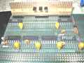
Hi B1. On the PM-1029B, you can see on the back of the DPM that there are 2 rows of 20 pins. That originally was for the 7107 40 pin dip. The manufacturer kept the PC board, but started to make their own IC (integrated on the PC board.)
You'll find in the App notes that the design is the same, but slightly modified. If you have a hand drawn schematic, you'll see that they are pretty much the same.
Anyway, I've included the links to the PDF files for the 7107 chip as well as the modification for making it a single supply common ground DPM. I hope this helps.
I've modified my 4 1/2 digit DPM by removing the single turn pot, and replacing with a multi-turn. I have a schematic of a modified PM-328 DPM (4 1/2 digit), that includes adjustment info. The circuit has basically the same design as the other DPMs. I've also added a crystal for stability.
The 4 1/2 digit LCD DPM uses the TC7129 chip = ICL 7129
TC7107 = 3 1/2 digit LED A/D convertor/display driver.
TC7106 = 3 1/2 digit LCD equivalent.
Telcom IC:
http://ww1.microchip.com/downloads/en/D ... 21455C.pdf (TC7107 datasheet and applications)
http://ww1.microchip.com/downloads/en/A ... 00783b.pdf (+5v Applications = common gnd)
Same IC:
Intersil, Harris, and Maxim = ICL7107
If you have any other questions, let me know.
evahle
-
flybyknight
- Posts: 3
- Joined: Mon Aug 23, 2010 3:37 pm
- Contact:
Re: PM-1029B Digital Panel Meter Questions
I see this thread is pretty old but here goes.
I too have the PM-1029A version of this meter.
It looks pretty straight forward.
I tried testing the meter with a 12 volt battery and used a 9 volt battery as my power supply.
The meter shows the voltage for a half second and then drops to 1
I tested several batteries and supplies and seem to get the same results.
I have the P2 jumped as instructed and the 9 volt power on the V+ and V-.
Power being tested is on the Vin and GND pad.
Any Ideas why this would happen?
I used 16 gauge wire because of the 12 volt motorcycle electrical system being tested. I realize this is over kill on the 9 volt side but its just a test and I had the leads already on the bench.
Thanks
Re: PM-1029B Digital Panel Meter Questions
flybyknight wrote:I see this thread is pretty old but here goes.
I too have the PM-1029A version of this meter.
It looks pretty straight forward.
I tried testing the meter with a 12 volt battery and used a 9 volt battery as my power supply.
The meter shows the voltage for a half second and then drops to 1
I tested several batteries and supplies and seem to get the same results.
I have the P2 jumped as instructed and the 9 volt power on the V+ and V-.
Power being tested is on the Vin and GND pad.
Any Ideas why this would happen?
I used 16 gauge wire because of the 12 volt motorcycle electrical system being tested. I realize this is over kill on the 9 volt side but its just a test and I had the leads already on the bench.
Thanks
Hi! The reason for the #1 is, it's an overvoltage indicator. Try this test: Using a resistor divider, reduce the input voltage from 12v to .1v, Then see if the display shows 100. If it does, then the jumper P2 is actually P1, or P1 is shorted, which sets the meter for 200mv display. Good luck!
-
flybyknight
- Posts: 3
- Joined: Mon Aug 23, 2010 3:37 pm
- Contact:
Re: PM-1029B Digital Panel Meter Questions
It does not matter which way I jump it P2 or P3 it only moves the decimal, or makes it appear.
Funny how the instruction say'
0.2 V jump p3
20 v jump p2
200 v jump p3
500 v jump _
I think it should read
0.2 v jump p1.
There is also a place on the board that had a place to jump
0.2v
20v
200v
500v
It came with the 0.2v jumped.
Do I assume it should be on 20 V for my needs?
Thanks for the quick responce.
Mark
-
flybyknight
- Posts: 3
- Joined: Mon Aug 23, 2010 3:37 pm
- Contact:
Re: PM-1029B Digital Panel Meter Questions
Yep, that was it.
I removed the solder blob off 0.2 V
And put one on 20 V
Now the voltage is reading correctly with the decimal correct as well.
The instructions say nothing about this jump.
You made me think of it because it has a resistor on the board next to these jumpers.
You mention putting a resitor to reduce the input voltage.
Thanks again,
Mark
Re: PM-1029B Digital Panel Meter Questions
flybyknight wrote:Yep, that was it.
I removed the solder blob off 0.2 V
And put one on 20 V
Now the voltage is reading correctly with the decimal correct as well.
The instructions say nothing about this jump.
You made me think of it because it has a resistor on the board next to these jumpers.
You mention putting a resitor to reduce the input voltage.
Thanks again,
Mark
You're welcome!
Who is online
Users browsing this forum: Google [Bot] and 33 guests