Hi all.
The 04/2001 issue of Poptronics may have a schematic using a CD4017 +ULN2003 to step a motor; can someone please confirm/describe circuit?
My 25+ year magazine collection is in storage far, very far...
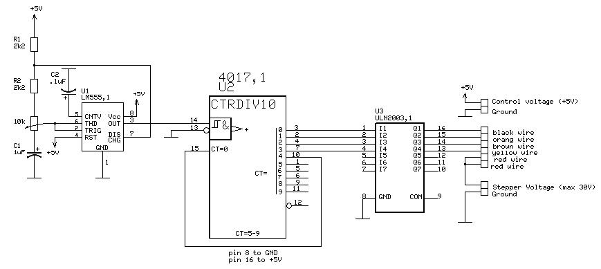
Is it like this one? :
http://www.bvsystems.be/stepper.jpg
Thanks,
Miguel
CD4017 used as stepper on Poptronics 04/01 ?
.
Eyyyyyy..Miguel...que Paaaaaaaaaaasa ?
Now quick scanning within those articles for that month I saw NONE that were specific in using that ULN200X series of interfacing..nor used as a pre motor driver..but just relevant to the 4017 aspect there was one article on it...with a further follow up the next month, but it was merely driving a large multiplexed mass of LED's
Wasn't sure which / if any of the following was applicable to your situation so I am sending you "the whole ball 'o twine"...and you can unravel it accordingly, should it pertain to your application .
Now looking within those articles.
The first application is certainly easier in its current consumption mode, with its incorporating a C-mos gate section as its osc.
Also, any further info as to the initial source that said that info was actually in that issue would be helpful.
Ref.....Pulled Oversized and then J-pegged up for clarity:
http://img228.imageshack.us/img228/499/4017pg16oc.jpg
http://img120.imageshack.us/img120/6789/4017pg25nb.jpg
http://img120.imageshack.us/img120/5889/4017pg36oe.jpg
http://img267.imageshack.us/img267/3710/4017pg43cm.jpg
73's de Edd
[email protected] ...........(Interstellar~~~~Warp~~~~Speed)
[email protected]..........(Firewalled*Spam*Cookies*Crumbs)
You can't have everything. Where in the world would you put it?.....
.
Miguel,
I have a circuit similar to that on my breadboard right now... I run two steppers and instead of the 4017 I use a PIC that simply does something like:
rb0 = 1;
rb4 = 1;
wait
rb0 = 0;
rb4 = 0;
rb1 = 1;
rb5 = 1;
wait
etc.
I used it to experiment with different voltages/delays to see how fast the motors could turn.
The stepper motors work fine. Your 555/4017 means they can only go one direction. I'm sure you know most of this though...
Hello Ed, thanks for being so kind taking the work of scanning the pages !
Seems I was misled, the article does correspond to the 4017 but not to drive a stepper motor with it.
Very nice from you, hope I can be of help any time.
Newz2000 : I may throw up with software, am avoiding PICs because of that.
Since I dumped my programmer title to the garbage can in 1971... been looking for a new brain .
I just need to step one step every minute from an atomic clock pulse, the 4017 should work just fine.
Cheers,
Miguel
A dual flip-flop can be used to generate the patterns for driving a stepping motor. It is wired as a two bit shift register, with the input to the first stage coming from the complement output of the second stage.
This gives the sequence:
00
10
11
01
00, etc.
The four outputs are (for two complete cycles):
01100110 (first stage true)
00110011 (second stage true)
10011001 (first stage complement)
11001100 (second stage complement)
This is known as a shift counter, Johnson counter, or switch tail ring counter.
This gives the sequence:
00
10
11
01
00, etc.
The four outputs are (for two complete cycles):
01100110 (first stage true)
00110011 (second stage true)
10011001 (first stage complement)
11001100 (second stage complement)
This is known as a shift counter, Johnson counter, or switch tail ring counter.
Who is online
Users browsing this forum: No registered users and 98 guests