Yes I believe I did. This may have come about due to the difference in the BS1-OEM and the BS1-1C. I've wired this up as I understand the schematic and following the pics you posted. I'm using a 7.5Vdc wall wart from Parallax. I wired this into the screw terminal header and connected the positive and negative to the two main strips on the perf board that go down the center of the board. This is what I thought you were suggesting in the article and from viewing Figure 7. Is this incorrect?
[after posting saw your edition to your previous]
You've provided me 3 options, the first two aren't that attractive because it requires me to procure more parts, the third has my interest. Can I just tie my P0 resistor to Vdd instead of the current main power bus on the perf board? Are the other pins okay to be tied to the main power bus as currently wired?
Thanks for the help.
Peanut Butter Monster Detector project questions
-
VernGraner

- Posts: 223
- Joined: Sun Mar 02, 2003 1:01 am
- Location: Austin Texas
- Contact:
Re: Peanut Butter Monster Detector project questions
I've taken the picture from figure 7 and enlarged, and labeled it here:mosimpson wrote:Yes I believe I did. This may have come about due to the difference in the BS1-OEM and the BS1-1C. I've wired this up as I understand the schematic and following the pics you posted. I'm using a 7.5Vdc wall wart from Parallax. I wired this into the screw terminal header and connected the positive and negative to the two main strips on the perf board that go down the center of the board. This is what I thought you were suggesting in the article and from viewing Figure 7. Is this incorrect?
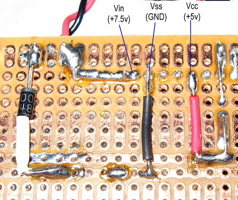
Though its a bit hard to make out, this shows that the V+ was applied to the OEM board and the OEM boards hefty regulator then provided the 5vdc used as V+ for that center bus. Hope That Helps.
Vern
--
Vern Graner
Vern Graner
-
VernGraner
- Posts: 223
- Joined: Sun Mar 02, 2003 1:01 am
- Location: Austin Texas
- Contact:
Re: Peanut Butter Monster Detector project questions
As you are using the Stamp to sink devices (LEDs) you should be ok.mosimpson wrote:Can I just tie my P0 resistor to Vdd instead of the current main power bus on the perf board? Are the other pins okay to be tied to the main power bus as currently wired?
Vern
--
Vern Graner
Vern Graner
Re: Peanut Butter Monster Detector project questions
Vern,
I stopped by Radio Shack on my way home and bought a 7805 Regulator I installed it and now have 5 Vdc at P0 and on the main distribution bus at the center of the perf board. My PBMD still just starts looping as described above when I plug it in. The code still seems to be blowing past the button command. P0 is 5 Vdc w/o the button pushed and 0 Vdc when pushed. Do you have anymore recommendations?
I stopped by Radio Shack on my way home and bought a 7805 Regulator I installed it and now have 5 Vdc at P0 and on the main distribution bus at the center of the perf board. My PBMD still just starts looping as described above when I plug it in. The code still seems to be blowing past the button command. P0 is 5 Vdc w/o the button pushed and 0 Vdc when pushed. Do you have anymore recommendations?
Re: Peanut Butter Monster Detector project questions
Do you have second PIC/BS2 to try?mosimpson wrote:P0 is 5 Vdc w/o the button pushed and 0 Vdc when pushed. Do you have anymore recommendations?
Applying too much voltage ot the input may have
toasted that part of the IC.
Plan B. Write a simple loop to read the port and
drive an LED. If the port and other hardware are
okay the LED will only change while the button is
pressed.
Re: Peanut Butter Monster Detector project questions
I am sure you have already checked this but... Are you 100% sure the button is connected to the correct pin?
Just a thought from someone who's been there
Kevin
Just a thought from someone who's been there
Kevin
Re: Peanut Butter Monster Detector project questions
Vern,
I've been trying to do some troubleshooting with P0. Is there a way to check the value of P0 through the computer? I've checked the hardware and I see it go from 5 Vdc to 0 Vdc when I push the button. I would now like to check the logic level on the BS1 to see if it changes value with a button push.
This troubleshooting has caused me to dig through the code and pay close attention to the sequence of operation of the program and it looks like there is also a problem with the LED's. For example, at the beginning of the program in the section labeled as 'Initialize' there is a line:
This line actually turns off the LED. I changed it to this and it works as the comment states:
I can change these statements to take care of the problems in the code but I'm unsure what to do with the 'Fade'.
It also appears at the beginning of the code in NoPress the LEDTrigger is instructed to "glow", I'm guessing this won't work properly but with my button problems I am unable to check.
I've been trying to do some troubleshooting with P0. Is there a way to check the value of P0 through the computer? I've checked the hardware and I see it go from 5 Vdc to 0 Vdc when I push the button. I would now like to check the logic level on the BS1 to see if it changes value with a button push.
This troubleshooting has caused me to dig through the code and pay close attention to the sequence of operation of the program and it looks like there is also a problem with the LED's. For example, at the beginning of the program in the section labeled as 'Initialize' there is a line:
Code: Select all
HIGH LEDtrigger ' Turn on trigger light to indicate INITCode: Select all
LOW LEDtrigger ' Turn on trigger light to indicate INIT MOD HIGH TO LOWCode: Select all
' ************************
' * Scan complete: Fade  *
' ************************
  DEBUG "FADE", CR
  HIGH LEDTrigger              ' Turn OFF the Button LED   MODIFIED LOW TO HIGH
  FOR cntI = 255 TO 0 STEP -1 ' Fade out the room lights
     FOR cntJ = 1 TO 20
       PWM LEDWHITE, cntI, 1  ' how long to dwell at each brightness level
     NEXT cntJ
  NEXT cntI
Re: Peanut Butter Monster Detector project questions
Good news, the buttons good!!  I checked it with this code:
Code: Select all
' {$STAMP BS1}
' {$PBASIC 1.0}

  Main:
    DEBUG "State of P0", #PIN0, CR

  GOTO Main
Re: Peanut Butter Monster Detector project questions
Vern-
I finally got the BUTTON command working in the code. Here's what I did:
I finally got the BUTTON command working in the code. Here's what I did:
Code: Select all
BUTTON Trigger, 0, 254, 150, btnWrk, 0, NoPress
Re: Peanut Butter Monster Detector project questions
Allright everythings working correctly now except the Radio Shack sound board. The new sound board Radio Shack sells has surface mount components so I was unable to solder to R3 like the article says. I overcame this by removing the button and soldering to one of the traces for the pushbutton. I bench tested this by shorting the soldered wire to Vss and the module triggered as exepected. However with the sound board hooked to P3 and the Stamp providing the path to ground I can't trigger it.  I tried changing the pause value with no success. Any ideas on how to get the sound board to trigger??
[After a short debug session]
I checked pin 3 with system powered P3 = 5V.
After pulling setting pin 3 LOW P3 = 2.5V.
How do I get it to drop to 0V when P3 is LOW?
[After a short debug session]
I checked pin 3 with system powered P3 = 5V.
After pulling setting pin 3 LOW P3 = 2.5V.
How do I get it to drop to 0V when P3 is LOW?
Re: Peanut Butter Monster Detector project questions
If P3 is a standard uC IO pin it should swing verymosimpson wrote:I checked pin 3 with system powered P3 = 5V.
After pulling setting pin 3 LOW P3 = 2.5V.
close to ground (logic zero) and very close to the
supply (logic one).
Have you tested it with nothing connected? Sounds
like a conflict with another port pin and/or driving
too much load. Have you checked for shorts or
solder bridges?
Who is online
Users browsing this forum: No registered users and 12 guests