I have some questions regarding amperage with some components that I want to use in my truck.
First, I found some indicator-lamp enclosures that have LEDs and resistors built-in. They are rated at 12v normal, 16v max, and something like 20ma. Am I right in assuming that these will work fine running off my truck's alternator, since it puts out a little more than 12 volts? Should I put an extra resistor in series just to be safe? Can I put it directly in parrellel with some high-amp lights, or should I give the LEDs their own part of the DPDT switch that the lights run off of? Or maybe they should even have their own fuse? If they can be run in parrellel, can I use small wires for the LEDs even though the lights have relatively thick wires?
Secondly, about the switches. I found some different toggle switches that I'd like to use for these lights and LEDs, but most are rated for something like 6 amps and 125vac. How would this compare to 12vdc? Don't you need beefier equipment for DC than AC? How can I measure the amperage of my lights? Should I use relays just to be safe? Assuming I know the amperage of the lights, what fuse should I use for them?
As an alternative to answering all of my questions one-by-one, maybe somebody could just tell me the best way to do this. I just want to run my roll-bar lights, back-up lights, and maybe some other electrical item off of some toggle switches on the dash. Each toggle should have a small light above it to tell you that it's on. I'd like to use LEDs, but it doesn't really matter if they're incandescent like the rest of the lights on the dash. And that's it. Any help would be appreciated.
Questions about amps and automotive components
Re: Questions about amps and automotive components
Greetings (No Name Supplied),
LEDs do require a ballast resistor, and the value is determined
by the required current (brightness) and the available supply
voltage.
a fully charged battery is actually 13.8V, and the alternator
will put out a higher voltage to charge the battery.
I suspect the 12V nominal, 16V max. spec of the LEDs
that you have is intended for automotive use. Go ahead
and use them without additional resistors, unless you find them
to be too bright at night. Extra resistors can be added to
lower the brightness.
supply is fused for the high current lamps and the LEDs
are on thinner wiring, that wiring does not have the
protection against overload (and a fire hazard). On the
other hand its silly to run thick wire everywhere...
Yes, you can put them in parallel to the high current
loads, and no you don't need a special switch or to use
a separate pole on the DPDT switch you mentioned.
Correct. The AC circuits (regardless of power level or
voltage) are easier to control than the equivalent DC
circuit, because an AC voltage passes through zero
each half cycle and will extinguish any arcing (compared
to a DC circuit).
Many switches have both AC and DC ratings on the
part or in the manufacturer's data. Automotive
switches are beefed up for low voltage use.
use a current meter (ammeter) either a single
range one (like you see on a dash board) or a
multimeter (VOM or DMM) provided it has a
high current range. Many don't! A 50 watt bulb
will draw a little over 4 Amps, so a 10 Amp range
meter is very handy.
Another method is to look at the bulbs and
calculate the amperage from the wattage,
and assume the voltage is 12V. I = P/V
(I = 50/12 = 4.16A for a 50W bulb).
Bulbs draw heavy current at turn on, due to the
cold filament. This can be twenty times the
current at hot, but its such a short pulse most
fuses will not trip. A rule of thumb is to double the
actual load, and go to the next larger stock size
fuse. A 50W lamp draws about four amps, so
8Amps would be double, I'd use a 10Amp fuse here.
either relays or power MOSFet transistors to
switch the high current loads. The relays
(or transistors) can then be driven by a
separate control circuit using smaller switches
and placing the LED pilot indicators on the same
low power circuit. This low power circuit would
have its own fuse for protection, and possibly
taken after the ignition switch or light switch
to force the new lights off when the key is
removed or the OEM headlights are out. Also,
the high current relays and their fuses can
be placed in another part of the vehicle to
make it easier to build.
A good example of high current after market
lights and other heavy loads in in any emergency
vehicle (Police car for example). If you can find
a tech at the Police or a city depot they would
show you how the pros do this kind of work.
Comments Welcome!
Peter
LEDs do require a ballast resistor, and the value is determined
by the required current (brightness) and the available supply
voltage.
Yes, the nominal voltage of an automotive battery is 12V, butzmwworm wrote:I found some indicator-lamp enclosures that have LEDs and resistors built-in. They are rated at 12v normal, 16v max, and something like 20ma. Am I right in assuming that these will work fine running off my truck's alternator, since it puts out a little more than 12 volts? Should I put an extra resistor in series just to be safe?
a fully charged battery is actually 13.8V, and the alternator
will put out a higher voltage to charge the battery.
I suspect the 12V nominal, 16V max. spec of the LEDs
that you have is intended for automotive use. Go ahead
and use them without additional resistors, unless you find them
to be too bright at night. Extra resistors can be added to
lower the brightness.
There's no easy answer to this one due to safety. If thezmwworm wrote:Can I put it directly in parrellel with some high-amp lights, or should I give the LEDs their own part of the DPDT switch that the lights run off of? Or maybe they should even have their own fuse? If they can be run in parrellel, can I use small wires for the LEDs even though the lights have relatively thick wires?
supply is fused for the high current lamps and the LEDs
are on thinner wiring, that wiring does not have the
protection against overload (and a fire hazard). On the
other hand its silly to run thick wire everywhere...
Yes, you can put them in parallel to the high current
loads, and no you don't need a special switch or to use
a separate pole on the DPDT switch you mentioned.
zmwworm wrote:Secondly, about the switches. I found some different toggle switches that I'd like to use for these lights and LEDs, but most are rated for something like 6 amps and 125vac. How would this compare to 12vdc? Don't you need beefier equipment for DC than AC?
Correct. The AC circuits (regardless of power level or
voltage) are easier to control than the equivalent DC
circuit, because an AC voltage passes through zero
each half cycle and will extinguish any arcing (compared
to a DC circuit).
Many switches have both AC and DC ratings on the
part or in the manufacturer's data. Automotive
switches are beefed up for low voltage use.
If you wish to know the actual current you canzmwworm wrote:How can I measure the amperage of my lights? Should I use relays just to be safe? Assuming I know the amperage of the lights, what fuse should I use for them?
use a current meter (ammeter) either a single
range one (like you see on a dash board) or a
multimeter (VOM or DMM) provided it has a
high current range. Many don't! A 50 watt bulb
will draw a little over 4 Amps, so a 10 Amp range
meter is very handy.
Another method is to look at the bulbs and
calculate the amperage from the wattage,
and assume the voltage is 12V. I = P/V
(I = 50/12 = 4.16A for a 50W bulb).
Bulbs draw heavy current at turn on, due to the
cold filament. This can be twenty times the
current at hot, but its such a short pulse most
fuses will not trip. A rule of thumb is to double the
actual load, and go to the next larger stock size
fuse. A 50W lamp draws about four amps, so
8Amps would be double, I'd use a 10Amp fuse here.
If it were my truck I'd strongly considerzmwworm wrote:I just want to run my roll-bar lights, back-up lights, and maybe some other electrical item off of some toggle switches on the dash. Each toggle should have a small light above it to tell you that it's on. I'd like to use LEDs, but it doesn't really matter if they're incandescent like the rest of the lights on the dash.
either relays or power MOSFet transistors to
switch the high current loads. The relays
(or transistors) can then be driven by a
separate control circuit using smaller switches
and placing the LED pilot indicators on the same
low power circuit. This low power circuit would
have its own fuse for protection, and possibly
taken after the ignition switch or light switch
to force the new lights off when the key is
removed or the OEM headlights are out. Also,
the high current relays and their fuses can
be placed in another part of the vehicle to
make it easier to build.
A good example of high current after market
lights and other heavy loads in in any emergency
vehicle (Police car for example). If you can find
a tech at the Police or a city depot they would
show you how the pros do this kind of work.
Comments Welcome!
Peter
Re: Questions about amps and automotive components
Thanks for the thorough reply!
What's the point in a username if everyone is going to sign their posts anyway? Besides, "Zach" is probably too common for me to get on every webboard, and I want to use the same name for everything.Bigglez wrote:Greetings (No Name Supplied),
Actually, I forgot about the way I hate having bright dash lights at night, so I'll probably end up using some extra resistors.I suspect the 12V nominal, 16V max. spec of the LEDs
that you have is intended for automotive use. Go ahead
and use them without additional resistors, unless you find them
to be too bright at night. Extra resistors can be added to
lower the brightness.
I don't think it would help to run larger-gauge wire anyway, since the leads of the resistors and LEDs are tiny, and they would be the weak point almost no matter what.There's no easy answer to this one due to safety. If the
supply is fused for the high current lamps and the LEDs
are on thinner wiring, that wiring does not have the
protection against overload (and a fire hazard). On the
other hand its silly to run thick wire everywhere...
I was just looking through the selection at Radio Shack, and all of their switches are rated for either 125vac, 250vac, or 12vdc. Unfortunately, there are very few that have a 12vdc rating, and the ones that I'd like to use are rated for 125vac, so any idea on how these will work at 12vdc?Many switches have both AC and DC ratings on the
part or in the manufacturer's data. Automotive
switches are beefed up for low voltage use.
I'll see if I can find the wattage rating on the lights. But assuming I can't, how do you measure current with a multimeter? Do you put the multimeter in series with the load and a battery, for instance? Or can it be measured just like resistance? Also, what guage of wire should I use for the lights, do I need to calculate the load and whatnot, or can I just take the size of the wires on the lights and get something about four times as large (since there are four lights)?If you wish to know the actual current you can
use a current meter (ammeter) either a single
range one (like you see on a dash board) or a
multimeter (VOM or DMM) provided it has a
high current range. Many don't! A 50 watt bulb
will draw a little over 4 Amps, so a 10 Amp range
meter is very handy.
Another method is to look at the bulbs and
calculate the amperage from the wattage,
and assume the voltage is 12V. I = P/V
(I = 50/12 = 4.16A for a 50W bulb).
I'll have plenty of room where the switches are. I think you're probably right though, relays would be the way to go. I guess I was just trying to avoid the hassle of more components. If I'm going to be getting lamps, switches, and relays then maybe it would be worth it to mail-order this stuff. Any recomendations for a company? I've looked through a Jameco catalog, but their switches are also mostly rated at 125vac. I've got an old fuse panel with an assortment of fuses so that shouldn't be a problem. I've also got a bunch of old relays from a car, but I don't know if any of them would be rated high enough for four roll-bar lights.If it were my truck I'd strongly consider
either relays or power MOSFet transistors to
switch the high current loads. The relays
(or transistors) can then be driven by a
separate control circuit using smaller switches
and placing the LED pilot indicators on the same
low power circuit. This low power circuit would
have its own fuse for protection, and possibly
taken after the ignition switch or light switch
to force the new lights off when the key is
removed or the OEM headlights are out. Also,
the high current relays and their fuses can
be placed in another part of the vehicle to
make it easier to build.
Re: Questions about amps and automotive components
Greetings Zach,zmwworm wrote:What's the point in a username if everyone is going to sign their posts anyway? Besides, "Zach" is probably too common for me to get on every webboard, and I want to use the same name for everything.Bigglez wrote:Greetings (No Name Supplied),
Good point, I wasn't trying to offend anyone - just seems odd to
me to have a conversation without knowing who is out there.
Comments Welcome!
Re: Questions about amps and automotive components
Greetings Zach,
to change the brighness of all instrument lamps. If so,
you can tap into that circuit and have your new pilot
lamps also dim.
wiring downstream from overload. If you have a
10Amp fuse and 10Amp wiring it's protected, but
if you add 1Amp wiring to the same circuit and
there is a fault on the 1Amp section the fuse won't
blow but the wiring might overheat.
I had in mind that it would be better to keep the
heavy wiring for the heavy loads (your new lights)
and use thinner wire for the control switches and
pilot lights, which would be on a second fuse.
contacts need to be far enough apart when open
to stop an arc. Obviously a 12V DC switch will
not need as much space as a 250VAC type.
So here you can used a higher voltage switch on
a lower voltage without error.
Secondly, the switches for lower voltage may
have more metal in the contacts to reduce the
resistance when closed. A voltage drop in the
switch (due to high current) will heat the switch
up and also reduce the available voltage for the
switch's load. So here its better to get a
switch designed for low voltage. Often the
switch is derated for DC compared to AC due
to arcing (even in low voltage circuits), as
noted earlier.
meter. Be careful! Many VOM or DMM meters are only
rated to 2A on the top current range. To go higher
you'll need an external current shunt (meter accessory).
the high temp of the filament increases the resistance,
so a "cold" resistance measurement would be meaningless.
of mind that your new wiring won't overheat. Most
likely the OEM wire on your new lights is a minimum
guage to reduce costs. Use the power transmission
column and go to the next larger size, or the next
larger size that you can buy easily.
For example a 12V 50W load draws a little over 4Amps,
from the table 15AWG is good for 4.7Amps, but a
12AWG wire (rated to 9.3Amps) is more common.
Most likely your new lights have only one wire each
and use the metal chassis of the truck body for ground.
In this case you have to power each light on its
own wire, and so the wire is rated for the current
of one light.
If your new lights have two wires you can bond one
to the truck chassis for ground, or connect one
wire from each light to a common wire and make
it 12V via a fuse. This supply wire will carry all the
current and should be bigger than the rating of
each light added together. This circuit uses more
wire, as you'll still need a dedicated run for each
new light and its switch. You will have to do a
fifth wire (for power or ground) if your new lights
are not on the chassis of the truck. I guess that
Corvettes and other non-metal cars have more
wiring!
they're both very good. Some items are available
from both so you can go with the lower price, and
Digikey has a min order penalty but Mouser doesn't.
Both have great paper catalogs (free) and on-line
tools to find current data, stock, and pricing.
and Halted (HSC) that offer great deals, but items run out and so
its hard to go back a year or three later and get more.
You can salvage parts from a junkyard, often relays
will have generic markings but with a bit of practice
you can spot the high current ones that you'll need here.
Comments Welcome!
One other thing, your OEM dash probably has a dimmerzmwworm wrote: Actually, I forgot about the way I hate having bright dash lights at night, so I'll probably end up using some extra resistors.
to change the brighness of all instrument lamps. If so,
you can tap into that circuit and have your new pilot
lamps also dim.
Agreed, but as I see it the fuse is to protect thezmwworm wrote: I don't think it would help to run larger-gauge wire anyway, since the leads of the resistors and LEDs are tiny, and they would be the weak point almost no matter what.
wiring downstream from overload. If you have a
10Amp fuse and 10Amp wiring it's protected, but
if you add 1Amp wiring to the same circuit and
there is a fault on the 1Amp section the fuse won't
blow but the wiring might overheat.
I had in mind that it would be better to keep the
heavy wiring for the heavy loads (your new lights)
and use thinner wire for the control switches and
pilot lights, which would be on a second fuse.
There's two criteria. Firstly, voltage. The switchzmwworm wrote: I was just looking through the selection at Radio Shack, and all of their switches are rated for either 125vac, 250vac, or 12vdc. Unfortunately, there are very few that have a 12vdc rating, and the ones that I'd like to use are rated for 125vac, so any idea on how these will work at 12vdc?
contacts need to be far enough apart when open
to stop an arc. Obviously a 12V DC switch will
not need as much space as a 250VAC type.
So here you can used a higher voltage switch on
a lower voltage without error.
Secondly, the switches for lower voltage may
have more metal in the contacts to reduce the
resistance when closed. A voltage drop in the
switch (due to high current) will heat the switch
up and also reduce the available voltage for the
switch's load. So here its better to get a
switch designed for low voltage. Often the
switch is derated for DC compared to AC due
to arcing (even in low voltage circuits), as
noted earlier.
Yes, you break the circuit under test and insert thezmwworm wrote: I'll see if I can find the wattage rating on the lights. But assuming I can't, how do you measure current with a multimeter? Do you put the multimeter in series with the load and a battery, for instance?
meter. Be careful! Many VOM or DMM meters are only
rated to 2A on the top current range. To go higher
you'll need an external current shunt (meter accessory).
I don't think that will help. When the bulb is operatingzmwworm wrote: Or can it be measured just like resistance?
the high temp of the filament increases the resistance,
so a "cold" resistance measurement would be meaningless.
Better to follow the wire spec tables and have the peacezmwworm wrote: Also, what guage of wire should I use for the lights, do I need to calculate the load and whatnot, or can I just take the size of the wires on the lights and get something about four times as large (since there are four lights)?
of mind that your new wiring won't overheat. Most
likely the OEM wire on your new lights is a minimum
guage to reduce costs. Use the power transmission
column and go to the next larger size, or the next
larger size that you can buy easily.
For example a 12V 50W load draws a little over 4Amps,
from the table 15AWG is good for 4.7Amps, but a
12AWG wire (rated to 9.3Amps) is more common.
Most likely your new lights have only one wire each
and use the metal chassis of the truck body for ground.
In this case you have to power each light on its
own wire, and so the wire is rated for the current
of one light.
If your new lights have two wires you can bond one
to the truck chassis for ground, or connect one
wire from each light to a common wire and make
it 12V via a fuse. This supply wire will carry all the
current and should be bigger than the rating of
each light added together. This circuit uses more
wire, as you'll still need a dedicated run for each
new light and its switch. You will have to do a
fifth wire (for power or ground) if your new lights
are not on the chassis of the truck. I guess that
Corvettes and other non-metal cars have more
wiring!
I often order mail-order from either Digikey or Mouser,zmwworm wrote: If I'm going to be getting lamps, switches, and relays then maybe it would be worth it to mail-order this stuff. Any recomendations for a company?
they're both very good. Some items are available
from both so you can go with the lower price, and
Digikey has a min order penalty but Mouser doesn't.
Both have great paper catalogs (free) and on-line
tools to find current data, stock, and pricing.
There are surplus dealers such as All Electronicszmwworm wrote:I've looked through a Jameco catalog, but their switches are also mostly rated at 125vac. I've got an old fuse panel with an assortment of fuses so that shouldn't be a problem. I've also got a bunch of old relays from a car, but I don't know if any of them would be rated high enough for four roll-bar lights.
and Halted (HSC) that offer great deals, but items run out and so
its hard to go back a year or three later and get more.
You can salvage parts from a junkyard, often relays
will have generic markings but with a bit of practice
you can spot the high current ones that you'll need here.
Comments Welcome!
Re: Questions about amps and automotive components
I thought of that, but I would like to be able to use these lights with the ignition and headlights off. I could run the LEDs through the dimmer anyway, but that would defeat the purpose (the lights could be on and the LEDs off, and the purpose of the LEDs is to keep me from draining my battery).Bigglez wrote:One other thing, your OEM dash probably has a dimmer
to change the brighness of all instrument lamps. If so,
you can tap into that circuit and have your new pilot
lamps also dim.
That clears things up in my mind. Speaking of which, part of the reason that I want to do this right the first time is that a significant number of wires in this truck have been melted together and were rewired by the previous owner, andI don't want to have the same thing happen to me. (By the way, this is an 1982 Toyota pickup in case it matters).Agreed, but as I see it the fuse is to protect the
wiring downstream from overload. If you have a
10Amp fuse and 10Amp wiring it's protected, but
if you add 1Amp wiring to the same circuit and
there is a fault on the 1Amp section the fuse won't
blow but the wiring might overheat.
So the best bet would be to get switches rated for 12VDC and avoid trying to make an AC switch work (or just use relays, of course).Secondly, the switches for lower voltage may
have more metal in the contacts to reduce the
resistance when closed. A voltage drop in the
switch (due to high current) will heat the switch
up and also reduce the available voltage for the
switch's load. So here its better to get a
switch designed for low voltage. Often the
switch is derated for DC compared to AC due
to arcing (even in low voltage circuits), as
noted earlier.
My multimeter can go to 10A. How likely is it that one of these lamps will draw more than that? (I'm cautious about destroying my brand new multimeter.) I can't find anything stamped or printed on them, the enclosures are BOSCH and are about 6 inches in diameter, and the bulbs look about 1/2 inch wide and 1-2 inches long (the refracting glass is hard to see through).Yes, you break the circuit under test and insert the
meter. Be careful! Many VOM or DMM meters are only
rated to 2A on the top current range. To go higher
you'll need an external current shunt (meter accessory).
What if the bulb was on and hot immediately before measuring resistance?I don't think that will help. When the bulb is operating
the high temp of the filament increases the resistance,
so a "cold" resistance measurement would be meaningless.
Using a wire stripper it looks like each light has two 16 gauge wires. The previous owner cut the grounds at just a couple inches and attached them to the mounting bolts, but I'm not sure that the rollbar will make a good ground with layers of paint and whatnot, so I'll probably wire them all to a common ground.Better to follow the wire spec tables and have the peace
of mind that your new wiring won't overheat. Most
likely the OEM wire on your new lights is a minimum
guage to reduce costs. Use the power transmission
column and go to the next larger size, or the next
larger size that you can buy easily.
For example a 12V 50W load draws a little over 4Amps,
from the table 15AWG is good for 4.7Amps, but a
12AWG wire (rated to 9.3Amps) is more common.
Most likely your new lights have only one wire each
and use the metal chassis of the truck body for ground.
In this case you have to power each light on its
own wire, and so the wire is rated for the current
of one light.
I'm sure that the wiring is the bare minimum needed to run the lights, but like you said before the fuse should match the wiring. I'd rather blow a fuse than melt wires and burn lights, so I might go with the wire rating even if the lights test higher. (Although if there is a significant discrepancy I'll have to run new wires for the lights).
By the chart, 16 gauge wire is probably 3.7 amps for each light. So I should probably run 10 or 9 guage (15A or 19A) wire if I put all four together. Also, that would be a 30A fuse and relay according to your recommendations (3.7A times 4 lights doubled = 29.6A). That seems kind of high, I don't think that there are any fuses over 20A in the truck right now. Maybe I should put a small fuse box after the single wire with 7.5A fuses for each light? (On a side note, can fuses be used in parallel to double the amps?)
That sounds good to me. What should I look for, something along the lines of larger contacts or heavier gauge wiring going to the relay?You can salvage parts from a junkyard, often relays
will have generic markings but with a bit of practice
you can spot the high current ones that you'll need here.
Re: Questions about amps and automotive components
Greetings Zach,
electronic displays (or dials with illuminated pointers
and number scales) you could use both. For daytime
use the LEDs would be full brightness (helping you
notice and not leave the light bar turned on), and
at night the LEDs track the dimmer to help you see
better without distracting bright LEDs.
As this is a bit more advanced, and may take some
experimenting, you can leave this to later, just run
the LEDs from an "always on" 12V feed (via a fuse).
12V capable switches third.
bulbs share the same glass dimensions yet have
different wattages. The data you are looking for
may be on the lamp base and only visible when
the lamp is out of the socket. Don't do this now, as
Quartz-Halogen bulbs fail if handled (due to oil from
fleshy fingers attacking the glass).
Its unlikely that a single bulb draws 10Amps, which
would be 120Watts. A high beam headlight is typically
55Watts.
You can play it safe and rig two of these lights in
series across the car battery. Both should light at
half power (assumes both are the same wattage).
Next, insert the ammeter on the 10Amp range and
note the reading. As long as it's under 5Amps you
can remove one light and power the other one
directly.
think there are too many variables to get good
results for your project.
I worked with an engineer that invented an electric
blanket heater controller using the resistance of the
heating element to judge the temperature and
control the power to keep the blanket cozy.
grounding (as you described) or busing to a
dedicated ground or 12V wire. Grounding to the
chassis is the easy way out (less wire!).
Its a bit of a stretch to use the wire gauge as a
pointer to the actual light wattage and current.
Better to measure the current and work from
there.
vintage truck only had smaller fuses. The original
ATO blade fuses go upto 30A, but for today's
vehicles it is not uncommon to have 80Amp
Maxi fuses or breakers.
nor can relay contacts but from time to time you
find this done. The easy route is to find an unused
fuse position in the existing fusebox and add your
project there. Perhaps your vehicle doesn't have
an electrical option that is already planned by the
standard fusebox assembly?
the junkyard is to find the label still on the fusebox
lid (or nearby). It details what the fuses are for
and the rating, some electrical loads will also
have relays. Here's one that I Googled at random.
Comments Welcome!
Here's an idea, as many contemporary vehicles havezmwworm wrote: I thought of that, but I would like to be able to use these lights with the ignition and headlights off. I could run the LEDs through the dimmer anyway, but that would defeat the purpose (the lights could be on and the LEDs off, and the purpose of the LEDs is to keep me from draining my battery).
electronic displays (or dials with illuminated pointers
and number scales) you could use both. For daytime
use the LEDs would be full brightness (helping you
notice and not leave the light bar turned on), and
at night the LEDs track the dimmer to help you see
better without distracting bright LEDs.
As this is a bit more advanced, and may take some
experimenting, you can leave this to later, just run
the LEDs from an "always on" 12V feed (via a fuse).
I'd go for MOSFets as first chioce , relays second, andzmwworm wrote:So the best bet would be to get switches rated for 12VDC and avoid trying to make an AC switch work (or just use relays, of course).
12V capable switches third.
Don't worry about the bulb data at this point. Manyzmwworm wrote:My multimeter can go to 10A. How likely is it that one of these lamps will draw more than that? (I'm cautious about destroying my brand new multimeter.) I can't find anything stamped or printed on them, the enclosures are BOSCH and are about 6 inches in diameter, and the bulbs look about 1/2 inch wide and 1-2 inches long (the refracting glass is hard to see through).
bulbs share the same glass dimensions yet have
different wattages. The data you are looking for
may be on the lamp base and only visible when
the lamp is out of the socket. Don't do this now, as
Quartz-Halogen bulbs fail if handled (due to oil from
fleshy fingers attacking the glass).
Its unlikely that a single bulb draws 10Amps, which
would be 120Watts. A high beam headlight is typically
55Watts.
You can play it safe and rig two of these lights in
series across the car battery. Both should light at
half power (assumes both are the same wattage).
Next, insert the ammeter on the 10Amp range and
note the reading. As long as it's under 5Amps you
can remove one light and power the other one
directly.
Yes, that would work it's an interesting idea!. Izmwworm wrote:What if the bulb was on and hot immediately before measuring resistance?
think there are too many variables to get good
results for your project.
I worked with an engineer that invented an electric
blanket heater controller using the resistance of the
heating element to judge the temperature and
control the power to keep the blanket cozy.
Sounds as if the lights were designed for eitherzmwworm wrote:Using a wire stripper it looks like each light has two 16 gauge wires. The previous owner cut the grounds at just a couple inches and attached them to the mounting bolts, but I'm not sure that the rollbar will make a good ground with layers of paint and whatnot, so I'll probably wire them all to a common ground.
grounding (as you described) or busing to a
dedicated ground or 12V wire. Grounding to the
chassis is the easy way out (less wire!).
.zmwworm wrote: By the chart, 16 gauge wire is probably 3.7 amps for each light. So I should probably run 10 or 9 guage (15A or 19A) wire if I put all four together.
Its a bit of a stretch to use the wire gauge as a
pointer to the actual light wattage and current.
Better to measure the current and work from
there.
Your math is right, and perhaps your 1982zmwworm wrote: Also, that would be a 30A fuse and relay according to your recommendations (3.7A times 4 lights doubled = 29.6A). That seems kind of high, I don't think that there are any fuses over 20A in the truck right now.
vintage truck only had smaller fuses. The original
ATO blade fuses go upto 30A, but for today's
vehicles it is not uncommon to have 80Amp
Maxi fuses or breakers.
Fuses can't be paralleled to increase amperage,zmwworm wrote:Maybe I should put a small fuse box after the single wire with 7.5A fuses for each light? (On a side note, can fuses be used in parallel to double the amps?)
nor can relay contacts but from time to time you
find this done. The easy route is to find an unused
fuse position in the existing fusebox and add your
project there. Perhaps your vehicle doesn't have
an electrical option that is already planned by the
standard fusebox assembly?
The treasure map for finding fuses and relays atzmwworm wrote:What should I look for, something along the lines of larger contacts or heavier gauge wiring going to the relay?
the junkyard is to find the label still on the fusebox
lid (or nearby). It details what the fuses are for
and the rating, some electrical loads will also
have relays. Here's one that I Googled at random.
Comments Welcome!
-
Robert Reed
- Posts: 2277
- Joined: Wed Nov 24, 2004 1:01 am
- Location: ASHTABULA,OHIO
- Contact:
ZWM
As to "My multimeter can go to 10A. How likely is it that one of these lamps will draw more than that? (I'm cautious about destroying my brand new multimeter.)"
Probably the only thing you destroy on overload is the shunt resistor in the meter. You can usually run higher currents for shorter periods with no ill effects. Example - the Flukes are rated at 10 amps continuous draw, but they permit 20 amps draw up to 30 seconds, probably higher and higher for shorter periods of time. Check your operating manual for max. current vs. time.
That's what I was planning on. If I was going to spend extra time working on my electrical system, I would try to get the horn and stereo working before I worried about having dimming LEDs.As this is a bit more advanced, and may take some
experimenting, you can leave this to later, just run
the LEDs from an "always on" 12V feed (via a fuse).
That's interesting, what advantages would MOSFets have over relays? I would think that if MOSFets were better suited for the job, then cars would use them instead of relays.I'd go for MOSFets as first chioce , relays second, and
12V capable switches third.
I've always wondered about if there are any other substances that do the same as skin oil. How do you personally handle them, with some sort of gloves or cloth?Don't do this now, as
Quartz-Halogen bulbs fail if handled (due to oil from
fleshy fingers attacking the glass).
I've managed to avoid grounding the bed so far by grounding the tailights to the frame, and I'd like to keep it that way for a number of reasons (one of which is so that a loose wire somewhere in the bed won't short out). For the lights I'll probably just run a common ground wire up to the cab where a connector will be anyway, and ground it right there to the cab or frame. Then I can use that same ground for my backup lights.Sounds as if the lights were designed for either
grounding (as you described) or busing to a
dedicated ground or 12V wire. Grounding to the
chassis is the easy way out (less wire!).
It may have been somewhat of a coincidence, but I just tested the lights and they're all around 3.8 amps, so my previous numbers should still be relevant.Its a bit of a stretch to use the wire gauge as a
pointer to the actual light wattage and current.
Better to measure the current and work from
there.
One of the fusible links would be a bit higher, but even then the alternator is only capable of 60 amps. Would there be any harm in using a 20A fuse, half-expecting it to blow? If it does I'll start looking for a 30A fuse, but if it doesn't then I'll know it works!Your math is right, and perhaps your 1982
vintage truck only had smaller fuses. The original
ATO blade fuses go upto 30A, but for today's
vehicles it is not uncommon to have 80Amp
Maxi fuses or breakers.
If I was just using two or three fuses that would work, but if I use a fuse for each light then I also have the parts to do it that way. I'm thinking I'll probably just try to use one fuse and relay, since using four fuses would probably work better with four relays as well, and that's getting overly complicated. (That's not including the extra fuse for the LEDs and switches, or the other accessories which will be used.)The easy route is to find an unused
fuse position in the existing fusebox and add your
project there. Perhaps your vehicle doesn't have
an electrical option that is already planned by the
standard fusebox assembly?
Fuses are easy that way, but I'm not sure about relays. I don't remember any label on the relay panel of the Tercel that I harvested. I do remember little schematics on each relay though, maybe I should dig them up any take a closer look.The treasure map for finding fuses and relays at
the junkyard is to find the label still on the fusebox
lid (or nearby). It details what the fuses are for
and the rating, some electrical loads will also
have relays.
Thanks for that info, I was a bit worried since I just about welded the probe on my multimeter to a boat-battery post while trying out those lights (just confirmation that halogen lights draw a lot of current when warming up!). But if I were to need a new shunt resistor, how hard would that be to replace? I don't think mine has a fuse, it even says "10A unfused" for the high-range lead (although it says "600ma fused" for the low range).Probably the only thing you destroy on overload is the shunt resistor in the meter. You can usually run higher currents for shorter periods with no ill effects. Example - the Flukes are rated at 10 amps continuous draw, but they permit 20 amps draw up to 30 seconds, probably higher and higher for shorter periods of time. Check your operating manual for max. current vs. time.
Greetings Zach,
vibration, etc. The auto industry has such a
large volume that their cost on the parts is
just a few pennies each, and PMOSFets cost
more.
Contemporary cars use a ton of PMOSFets,
some in place of relays and others to make
the interface to microcontroller electronics easier.
Automobiles are a harsh enviroment for any
electronics.
be 13.8 * 3.8 = 52.4Watts each.
On a 12V battery we can assume the bulbs are
52.4 * (12/13.8) = 46Watts. Probably the
'bogey' (design centre) is 50Watts.
BTW, although the alternator is rated to 60Amps,
the battery can produce much greater current
to turn a cold engine with the starter. The CCA
(Cold Cranking Amps) rating for many car
batteries is ten times the alternator rating.
for each circuit. You only need one fuse for all lights,
unless you wish to split the project into two or more
fused circuits. Auto makers work hard to reduce the
component count and cost (and doing so increases
the reliability for free).
the factory and not to any known standard. Often
the colour of the case is used to indicate 'size'
(Amperage).
Comments Welcome!
Relays are mechanical, and prone to wear,zmwworm wrote: That's interesting, what advantages would MOSFets have over relays? I would think that if MOSFets were better suited for the job, then cars would use them instead of relays.
vibration, etc. The auto industry has such a
large volume that their cost on the parts is
just a few pennies each, and PMOSFets cost
more.
Contemporary cars use a ton of PMOSFets,
some in place of relays and others to make
the interface to microcontroller electronics easier.
Automobiles are a harsh enviroment for any
electronics.
Either will work. A paper towel or tissue is also good.zmwworm wrote:I've always wondered about if there are any other substances that do the same as skin oil. How do you personally handle them, with some sort of gloves or cloth?
A fully charged battery is 13.8V so the bulbs wouldzmwworm wrote: It may have been somewhat of a coincidence, but I just tested the lights and they're all around 3.8 amps, so my previous numbers should still be relevant.
be 13.8 * 3.8 = 52.4Watts each.
On a 12V battery we can assume the bulbs are
52.4 * (12/13.8) = 46Watts. Probably the
'bogey' (design centre) is 50Watts.
Good idea! I suspect a 20Amp fuse would work.zmwworm wrote:One of the fusible links would be a bit higher, but even then the alternator is only capable of 60 amps. Would there be any harm in using a 20A fuse, half-expecting it to blow? If it does I'll start looking for a 30A fuse, but if it doesn't then I'll know it works!
BTW, although the alternator is rated to 60Amps,
the battery can produce much greater current
to turn a cold engine with the starter. The CCA
(Cold Cranking Amps) rating for many car
batteries is ten times the alternator rating.
You need a relay (or PMOSFet, or heavy duty switch)zmwworm wrote: If I was just using two or three fuses that would work, but if I use a fuse for each light then I also have the parts to do it that way. I'm thinking I'll probably just try to use one fuse and relay, since using four fuses would probably work better with four relays as well, and that's getting overly complicated. (That's not including the extra fuse for the LEDs and switches, or the other accessories which will be used.)
for each circuit. You only need one fuse for all lights,
unless you wish to split the project into two or more
fused circuits. Auto makers work hard to reduce the
component count and cost (and doing so increases
the reliability for free).
Good idea, but the OEM parts may be coded forzmwworm wrote:Fuses are easy that way, but I'm not sure about relays. I don't remember any label on the relay panel of the Tercel that I harvested. I do remember little schematics on each relay though, maybe I should dig them up any take a closer look.
the factory and not to any known standard. Often
the colour of the case is used to indicate 'size'
(Amperage).
Better to look after it and not have to make a repair...zmwworm wrote:I don't think mine has a fuse, it even says "10A unfused" for the high-range lead (although it says "600ma fused" for the low range).
Comments Welcome!
Okay, new stuff here but it's still about my truck. I've been trying to get my gauges and stuff working and it looks like I've got just about everything. Except for probably the most important dash component, and that is the idiot light. The problem is that I'm not exactly sure what year of engine I have, at the very least it's not the same as my truck and it is likely several different years worth of parts. I can't find the oil pressure switch that controls the idiot light. In the Chilton's manual there is a diagram for the 84-85 that does not show an oil pressure switch, only a sender for a guage, so maybe this is the engine block that I have (or maybe it's a mistake in the book, which is not out of the question).
My oil pressure sender and gauge work perfectly. There is positive from the battery going to the gauge, which connects to the sender which provides resistance to ground depending on oil pressure. Now I'm not sure if all oil senders work this way or if it's actually because this engine has a combined switch and sender, but when the engine is off there is absolutely no continuity between the sender and ground, just like a pressure switch. Once the pressure is built up, the sender gives about 100 ohms of resistance at idle. So what I want to do is run my light off of the sender, so the light is on when the sender is off, and the light goes out once the sender get pressure and provides resistance to ground.
This seems simple enough to just use a relay and run the light off of the normally-closed contact. But my concern is that connecting a relay in series with the gauge will make the gauge read too low (too much resistance). I'm assuming that relay coils have significant resistence since the coils do not create a short between positive and ground when you flip any switch in your car, and even if this resistance is just a few dozen ohms it will throw off the gauge (since the sender itself gives 100 ohms at idle pressure and probably even less at normal pressure). So what am I to do? What is the resistance of a typical relay, and if there's no way around it then would it be possible to connect the relay in parallel with the gauge to at least reduce the problem? Or is there a completely different and better way to get my idiot light to work?
Greetings Zach,
gauge is a constant resistance and the sender varies.
By ohm's law the voltage across each (the sender and the gauge)
will vary in proportion to the sender's resistance.
Use your voltmeter (DMM) to measure the voltage from sender
to ground at different oil pressures (engine speeds).
coil (out of the truck). You may find its 100 Ohms, but that's
a guess on my part.
an amplifier, one that doesn't load the sender and has enough
current to drive the relay. A single transistor will do this, or
at worst two transistors together, plus a few other components.
At this point the relay can be eliminated and use the
transistor amplifier to drive the pilot lamp directly.
The design of the amp is not trivial nor is it complex, the starting
point is the data you will be collecting above.
Comments Welcome!
The sender and the gauge form a resistive divider, where thezmwworm wrote: but when the engine is off there is absolutely no continuity between the sender and ground, just like a pressure switch. Once the pressure is built up, the sender gives about 100 ohms of resistance at idle. So what I want to do is run my light off of the sender, so the light is on when the sender is off, and the light goes out once the sender get pressure and provides resistance to ground.
gauge is a constant resistance and the sender varies.
By ohm's law the voltage across each (the sender and the gauge)
will vary in proportion to the sender's resistance.
Use your voltmeter (DMM) to measure the voltage from sender
to ground at different oil pressures (engine speeds).
Again, use your DMM on the ohms range to measure a relayzmwworm wrote:What is the resistance of a typical relay, and if there's no way around it then would it be possible to connect the relay in parallel with the gauge to at least reduce the problem?
coil (out of the truck). You may find its 100 Ohms, but that's
a guess on my part.
The relay is a good idea, but to drive the relay you'll needzmwworm wrote:Or is there a completely different and better way to get my idiot light to work?
an amplifier, one that doesn't load the sender and has enough
current to drive the relay. A single transistor will do this, or
at worst two transistors together, plus a few other components.
At this point the relay can be eliminated and use the
transistor amplifier to drive the pilot lamp directly.
The design of the amp is not trivial nor is it complex, the starting
point is the data you will be collecting above.
Comments Welcome!
That measurement is going to have to wait until I get a chance to take apart the dash.Bigglez wrote:Use your voltmeter (DMM) to measure the voltage from sender
to ground at different oil pressures (engine speeds).
I would like to have a failing circuit (solder breaking loose or something) result in (for the most part) lighting the lamp. So I'd probably want to use a relay. The light already has power, the original pressure switch just grounded the light directly to turn it on. If the relay circuit runs off of it's own fuse (probably the same as the one for my switches and LEDs), then the light will stay on even if the fuse blows or something similar happens (rather than a simple transistor amplifier, which would not). Actually, there's probably a way to make a transistor work exactly like a relay, I just don't know enough about electronics to do it. Besides, I have a selection of relays available, all with 60-70 ohms resistance.The relay is a good idea, but to drive the relay you'll need
an amplifier, one that doesn't load the sender and has enough
current to drive the relay. A single transistor will do this, or
at worst two transistors together, plus a few other components.
At this point the relay can be eliminated and use the
transistor amplifier to drive the pilot lamp directly.
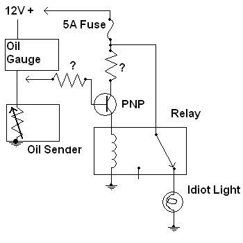
So here's a diagram I made up real quick with MSPaint. The arrows show where I would connect my circuit. Would this even work, or does a PNP turn off when positive voltage is applied? If this would work, do I need the resistors and what resistance? Again, is there a completely different and better way to do this?
Who is online
Users browsing this forum: No registered users and 155 guests