Page 1 of 1
Resistance meter question?
Posted: Thu Feb 10, 2005 6:58 pm
by telcotech
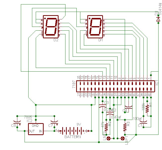
Hello,<p>I am in need of a schematic for a 2 digit 7-segment LED digital resistance meter....<p>I had a simple home-made wire mapper, it used rj11 plugs with resistors from 10k to 200k connected between pins 4 and 5, which read as 1 - 20 on the meter, the meter was housed in a small plastic project enclosure and used what I believe was a 7107 chip 2 - 7 segment LED's and a few resistors and caps. The PCB was a homemade 1 sided board. I found this a couple of years ago at a business auction in the bottom of a toolbox, it was slightly corroded but it worked. Curious as I am, I opened it up and looked at it only once about 2 years ago, I should have probably payed more attention then, anyway, about a year ago, it got lost, or, may have gotten into the hands of another curious tech who may have forgot to return it....<p>Anyway, I have been trying unsuccessfully to build another one.<p>I believe I could use a maxim max139cpl, max140cpl or icl7107cpl chip to do the ADC and drive a 2 digit 7-segment LED. It only needs to read 10k - 200k in whole numbers, 10k incraments, 10-19.999k would be 1, 20 -29.999k would be 2.... I believe the original design was based on 10k incraments to allow for various wire lengths and gauges. It was originally powered by 4 AA batteries, but I thought 1 9v might be better.<p>Any help, or anything in the way of a schematic would be greatly appreciated.<p>Here is a schematic I did, it needs some help, but it might be a good start. Any corrections or other ideas would be helpful.<p>Thanks<p>
Re: Resistance meter question?
Posted: Fri Feb 11, 2005 8:51 pm
by russlk
A 3 1/2 digit ohmmeter only costs a few bucks, why bother making your own?
Re: Resistance meter question?
Posted: Sat Feb 12, 2005 8:28 am
by philba
I dont disagree that as a project this doesn't necessarily make economic sense. However there are cases where I can see value.<p>One case is for low light situations. Even with a back light, my LCD DMM is hard to read. Using 7Segment LED displays would be significantly more readable. I've not seen cheap LED display DMMs.<p>An even more interesting project is a talking DMM for when your craining your head under the car hood or other places where its hard to probe and look at a meter.<p>And if telcotech wants to build one for fun and learning, I say go for it. So what if he's reinventing the wheel?<p>Lets be honest, many many things we can build are certainly easier to buy pre-made. And often, less expensive, too. But then, if I cared about that, I probably wouldn't be here.
Re: Resistance meter question?
Posted: Sat Feb 12, 2005 8:46 am
by philba
I got curious about the 7107 and looked it up. Pretty neat chip. Its a huge chip (40 pins) but if you dont want to mess with a uC, it's not a bad approach. I think it might be discontinued (Mouser seems to think so but others like Allied doesn't say) By the way JDR has it for $2.39 - significantly below everyone else.<p>Have you looked over the datasheet?
http://www.intersil.com/data/fn/fn3082.pdf. It's got a lot of info including quite a few application circuits. With out diving into your circuit, I'm sure it has the answer somewhere for you.<p>One question - why only 2 digits? Reading the datasheet, it can easily drive 3 1/2 and 7segment displays are pretty cheap.
Re: Resistance meter question?
Posted: Sat Feb 12, 2005 12:29 pm
by Mike6158
If I understood the post right, he's not looking for an ohm meter. He wants to build a wire mapper. Here's how it works. You attach a box on one end of a multiconductor cable. The box has a common and usually up to 10 or 12 numbered wires coming out of it. Clip the common on the shield wire or a common wire and then clip each of the numbered wires to a different wire in the bundle. No go to the other end and connect the "sensor" end common wire to the shield and start touching the wires with the probe. The display will will come up with a number that correlates to the numbered wire on the other end. You've now identified wire #X... Move to the next wire.<p>Crappy explanation but I'm pretty sure that's what he is looking for. He doesn't have enough parts to do what he needs to if that's what he's looking for.<p>If that's not what he's looking for... never mind.

Re: Resistance meter question?
Posted: Mon Feb 14, 2005 5:50 pm
by telcotech
The wiremapper works like this:<p>You take resistors starting with 10k, using rj11 plugs, you crimp the resistor across pins 4 and 5.<p>Take a straw, cut it into 1/2" to 3/4" pieces, put a piece over the resistor, fill the straw up with epoxy. This seals the resistor and bonds the straw to the resistor and the plug. when it dries, take a labeler and number the plugs, 10k would be #1, 20k #2.... Make as many as you want, I used 25, in 10k incraments.<p>Plug the plugs into jacks at various locations, goto the room you pulled all the wires to, strip white/blue and use the wiremapper to read each cable.<p>This can be used to map anything, cat3, cat5. You can also use rj45 plugs for networking or coax connectors. I made a few adaptors that plugged into electrical outlets when I wired a house and I could tell which wire went to which room.<p>This mapper came in handy many times, that's why I want to replace it.
Re: Resistance meter question?
Posted: Mon Feb 14, 2005 5:52 pm
by telcotech
2 digits were sufficient, you could map 99 cables, I guess if it was 3 digits, it might come in handy at some time though.