Page 1 of 1
I can't think today.. help !
Posted: Wed Aug 07, 2019 7:11 am
by dacflyer
ok,, here's what i got in mind, i want to make a led volt meter, using 3 leds. i'm looking for a dot mode type operation,
led 1= 5v, led 2= 9v, led 3= 12v i thought to use a LM324. but it only operates in linear mode, I could use a LM3914 in dot mode and just use 3 leds so that only 1 led is on at a time. but i'll never get it to operate like i want.
I'm even open to use just transistors. but i can't think how i can get 1 led on at a time, and when voltage is out of range for 1 led, then it turns off.
only 1 led is on within a small range.
any ideas ?
Re: I can't think today.. help !
Posted: Wed Aug 07, 2019 11:18 am
by Externet
Hi.
It could be better approached as three window comparator circuits.
One between 4.9 and 5.1 V to turn on led '5V' ;
One between 8.8 and 9.2 V to turn on led '9V' ;
One between 11.7 and 12.3 V to turn on led '12v' ;
or with the tolerances of your preference.
If that fits your wishes... Perhaps a LMV7231
Re: I can't think today.. help !
Posted: Thu Aug 08, 2019 9:12 pm
by dacflyer
i was thinking to use the LM324 for off the shelf use.. but no way to make it for 1 led at a time. as voltage goes up,, all 3 leds will light up.
only way i can think of a way for 1 led at a time and a small range to stay on is with a micro..
Re: I can't think today.. help !
Posted: Fri Aug 09, 2019 12:49 pm
by haklesup
you can also use a uController with integrated ADC and at least 3 IO lines. Likely much more accurate than an all analog thing. Try a USB based dev kit to keep the costs low, Microchip, TI, ST Micro, adafruit, sparkfun, arduino, R-Pi take your pick. Some research to select the best fit but there are many under $15 and dev tools are generally free.
https://www.digikey.com/products/en/dev ... =dev%20kit
Better selection tools and charts are on each respective manufacturer websites or datasheets on the digikey links
if you want to do it with an op amp, you'll need to use a transconductance amplifier configuration and put different dropping resistors on each LED. The voltage will be converted to current and each LED will light at a different threshold as determined by resistor offset, you won't ever get snap on and off or good accuracy or even linearity this way without simulating a but first.
Re: I can't think today.. help !
Posted: Fri Aug 09, 2019 4:27 pm
by CeaSaR
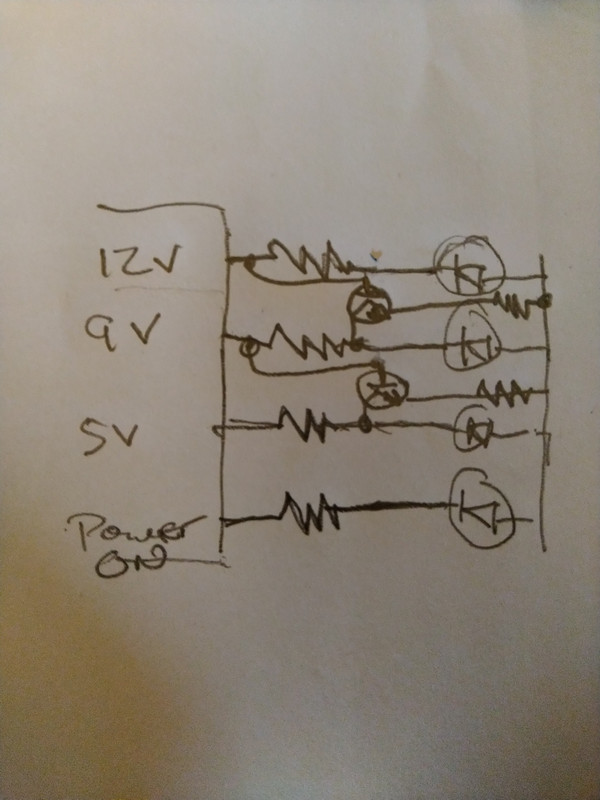
Go back to the "ok, new project time" thread (
viewtopic.php?f=45&t=17714 ) and look at the LM 324 circuit. Just use 1/2 of the shown circuit, but insert a NPN transistor and possibly a resistor as a switched path to ground, effectively grounding the input to the led.
Here's a quick sketch
Re: I can't think today.. help !
Posted: Sun Aug 11, 2019 11:50 am
by Joseph
I think that type of way is good
Re: I can't think today.. help !
Posted: Mon Aug 12, 2019 6:38 am
by dacflyer
so is that basically just shorting out the led ?
Re: I can't think today.. help !
Posted: Mon Aug 12, 2019 8:34 am
by CeaSaR
Yep, but it retains some resistance to ground because the LED resistor stays in circuit to prevent overloading the output. Since the signal to turn on is taken from the next step up, it'll turn the lower one off, and as the voltage increases, the lower outputs stay active, continuing to shunt the LED power to ground, hence they stay off untill the voltage drops down again.
The only other thing you may need is a resistor on the base to the transistor if, in use, it draws down the voltage too much to light the appropriate LED.
Re: I can't think today.. help !
Posted: Mon Aug 12, 2019 11:23 am
by dacflyer
ok, thanks, i'll try that
Re: I can't think today.. help !
Posted: Sun Oct 27, 2019 6:27 am
by CeaSaR
Did that ever work?
If it did, what was your final design?
Re: I can't think today.. help !
Posted: Mon Oct 28, 2019 5:02 am
by dacflyer
I went with using the LM324 and 4 leds. this way i was able to calibrate each led.
I really would have liked to have the last led to start blinking when the fuel got critically low.
But i can't think out how to go about it..
Right now the 4 leds are set at 20% 40% 60% 80% plus... ( the sensor actually pegs out at 75%, any reading above that doesn't change )
the bottom end will still read down to about 2%, but i try to not let it get that low.
So i'd like the lowest led (20% would start to blink at 5%) i can't think yet on how to do this..it'll come to me, just need time to sit and think.
but as it is right now works ok,, i'm planning to build it into an old thermostat housing.