
*Moving this here in hope of a response.
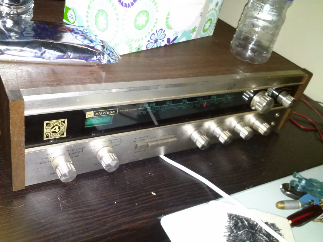
I have aquired a Claricon 27901 four channel receiver. No date code found yet. This is a really nice unit. Only thing is that one of the rear channels (I think rear right) doesn't work in 4-channel mode and when you put it in stereo only (2-channel) it only has one channel sometimes and it might be fuzzy or weak. So right now it is on 4-channel mode with just the fronts working perfectly.
I am inclined to believe that the problem is either in the preamp section or in the selector switch on the back panel that chooses between stereo and 4-channel. With no input and a speaker connected to the outputs, each one has hiss in all modes. So, any help is appreciated.
Thanks in advance,
CeaSaR
Info / schematic request
Info / schematic request
Hey, what do I know?
-
Janitor Tzap

- Posts: 1707
- Joined: Sat Aug 12, 2006 5:17 pm
- Contact:
Re: Info / schematic request
Hail CeaSaR!
Is that number the only one on the Claricon?
For they're stereo equipment it is normally in this type of numbering: XX-####7.
The Number you gave, looks like it is one of they're CB Radios.
I'm guessing this is early Transistor Unit, Circa 1970 - 1972.
I would first try cleaning the Speaker Switches, Function Switches, and spray the Volume, Bass, Treble, and any other Tone Controls.
If that doesn't solve the problem.
Get a tone generator and inject 1Khz Tone in to the Aux Inputs (Left & Right),
of the Pre-Amp.
With a Signal Tracer and check the signal coming out of each channel in the pre-amp.
If the Signal is fine, then move on to the Main Amplifier, and start checking the signal coming out of each Channel till you can isolate the channel that is causing the distortion.
Given the age of the unit, look for failed Electrolytic Capacitors, or burned Resistors.
As well as bad transistors.
One thing I found with these old Quadraphonic units is that once you repair one channel,
the components in the other channels may fail because they are weak from old age.
Thus, you could be looking at a total rebuild, replacing the worn out Electrolytic Capacitors, and resistors that are open or out of tolerance on the other channels.
Signed: Janitor Tzap
Re: Info / schematic request
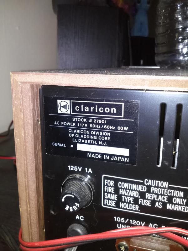
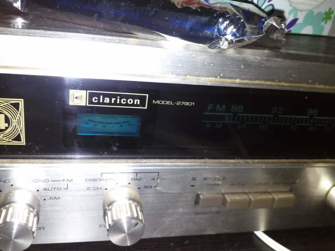
Well, unless my eyes have gone bad, that is the number of the unit. Let's have a look:
https://i.postimg.cc/wvHpCX8S/claricon27901frt.jpg
https://i.postimg.cc/rmq9x3cK/claricon27901bk.jpg
https://i.postimg.cc/qRpN1dNH/claricon27901namnum.jpg
I figured on doing some tracing and an eventual recap. It would be nice to have a schematic but none of my usual searches turned up anything. This is one tough bugger to track down.
I also plan on some general clean up, but it is rather quiet already. Gotta get a new can of cleaner - the old one is long since outta breath.
Thanks for the help. Anyone know where I can find documentation on this unit?
CeaSaR
Hey, what do I know?
-
Janitor Tzap
- Posts: 1707
- Joined: Sat Aug 12, 2006 5:17 pm
- Contact:
Re: Info / schematic request
Hmmm............
This must be one of a limited run that were made.
Because normally Sams PhotoFacts would cover the model if more that 2000 units were made.
From what else I found, the company went out of business back it 1993.
Here's an old address:
GLADDING-CLARICON, INC.
663 DOWD AVE.
ELIZABETH NJ 07201
Sorry,
That's the all I'm finding.
Check several of the Audio Forums and see if anyone has a schematic that they can make a copy for you.
Signed: Janitor Tzap
Re: Info / schematic request
Been to a couple searching, but most only have questions or links to the speakers made by Claricon.
Time to dive into one of them, I guess.
Thanks JT.
CeaSaR
Time to dive into one of them, I guess.
Thanks JT.
CeaSaR
Hey, what do I know?

Re: Info / schematic request
signal tracing is the method most likely to discriminate between an open at a trace or switch and an amplifier that is not working or a feedback short that's shutting down the channel. This looks a lot like the Marantz of the day and that used a large SIP package monolithic amplifier. If you can, post a few snapshots of the inside of that set. You might also look for the datasheet for the main amplifier, the manufacturer may have just copied the reference circuit and your set may be similar enough to work with.
Powered off continuity testing will be an easier way to test the selector switches and pots as well as various interconnects and tract to pin continuity. But you'll need to power up at some point to see how far a signal gets. Back in the days, multi layer boards were rare and silkscreen was often useful, visual circuit tracing should be possible.
Powered off continuity testing will be an easier way to test the selector switches and pots as well as various interconnects and tract to pin continuity. But you'll need to power up at some point to see how far a signal gets. Back in the days, multi layer boards were rare and silkscreen was often useful, visual circuit tracing should be possible.
-
Janitor Tzap
- Posts: 1707
- Joined: Sat Aug 12, 2006 5:17 pm
- Contact:
Re: Info / schematic request
Good idea.haklesup wrote: This looks a lot like the Marantz of the day and that used a large SIP package monolithic amplifier. If you can, post a few snapshots of the inside of that set. You might also look for the datasheet for the main amplifier, the manufacturer may have just copied the reference circuit and your set may be similar enough to work with.
But if memory serves me right.....
The SIP Amplifier packs didn't start showing up till around 1977 through the 1980's.
This looks to be early 70's, and those normally used discrete transistors.
Also the cabinet and front face plate look similar to Scott Stereo's or MCS of that vintage too me.
But yeah, there were a lot of stereo builders that bought components and boards from other manufacturers for their own brand.
Not to mention having some other company make the stereo, and just stamp they're own name on it.
Signed: Janitor Tzap
-
dacflyer

- Posts: 4748
- Joined: Fri Feb 08, 2002 1:01 am
- Location: USA / North Carolina / Fayetteville
- Contact:
Re: Info / schematic request
i used to have a old 70's pioneer home stereo,.it was a monster..rated at 650 watts per channel
its main failures were the toroid or the PS components would fail if it was maxed out for too long.
this unit was not repairable. but i did salvage some neat stuff like the giant lighted VU meters and the beer can sized PS caps, it had 4 of them in it. the VU meters i plan to make them into a nice cabinet and sit them on top of my stereo for that nostalgic flash back..the meters were VU and power scaled

Re: Info / schematic request
I'm guessing here, but I think that ou have 3 of 4 amplifiers working. The remaining one is "blown" but maybe not too badly.CeaSaR wrote:*Moving this here in hope of a response.
I am inclined to believe that the problem is either in the preamp section or in the selector switch on the back panel that chooses between stereo and 4-channel. With no input and a speaker connected to the outputs, each one has hiss in all modes. So, any help is appreciated.
You hear distortion in stereo mode because the LF and LR amps are wired in bridged mode for higher power, and your whole right channel signal should then sound distorted.
It could be a simple fix. Check the 2 emitter resistors in the blown channel. They should measure < 1 Ohm. Here's a real wild guess: The problem may all be due to an open collector on the bad channel's NPN output transistor. That's the transistor that starts with 2SA..... or 2SB..... If that is the problem, just relace that one Xistor.
-=VA7KOR=- My solar system includes Pluto.
Re: Info / schematic request
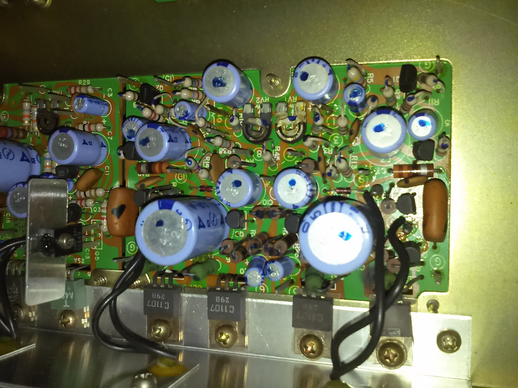
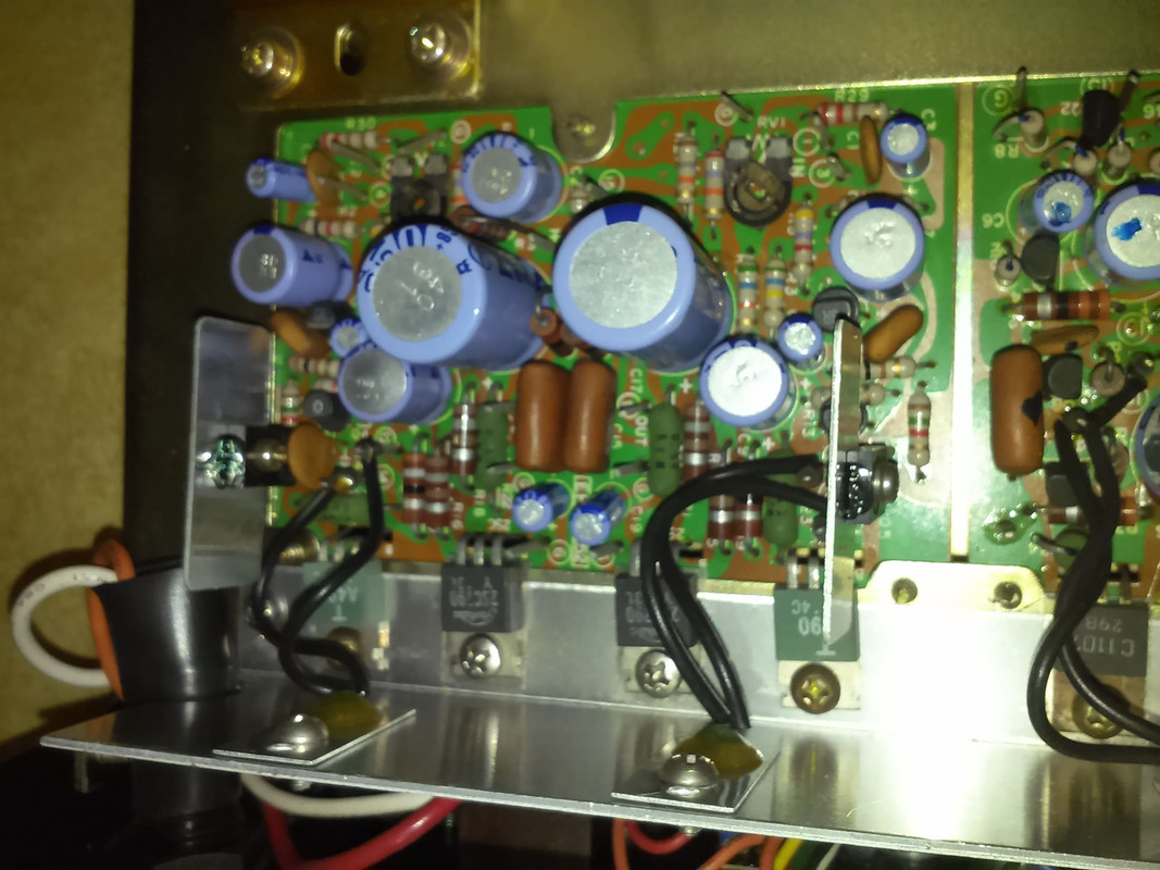
Well, I was finally able to pry this away from my son as he blew the fuse on it and what seems to be he toasted a pair of output transistors. Now that it is on my hands I am finally going to recap it - at least one is bad and a few others are looking suspicious. Here's the dilemma, I cannot find a good cross reference for the outputs. The ones that cooked are Sanken C1107 and either 29B or 298. Closest I am finding as possible are NTE196 or NTE377, but that is in a roundabout fashion being 2 or more removed from direct replacement. Any ideas guys?
Here's a few pics of the amp section. I'll update tomorrow with a few better and maybe some of the underside.
https://i.postimg.cc/G2dJB5fg/Claricon-Amp-Main.jpg
https://i.postimg.cc/RF4yMGL4/Claricon-Amp-Rear.jpg
Thanks,
CeaSaR
Here's a few pics of the amp section. I'll update tomorrow with a few better and maybe some of the underside.
https://i.postimg.cc/G2dJB5fg/Claricon-Amp-Main.jpg
https://i.postimg.cc/RF4yMGL4/Claricon-Amp-Rear.jpg
Thanks,
CeaSaR
Hey, what do I know?

Re: Info / schematic request
Quadraphonic. Full 'discrete' components. IC's maybe only for FM tuner section.
Set its mode to straight 4 channel aux, you should have FL, FR, RL, RR inputs that can be independently signal traced all the way to finals.
Good to have healthy channels to compare signals and voltages to find the fault.
Like my quadraphonic '71 Marantz
If everything fails, ask these people:
Check the pictures if any fits the same geometry of controls; may be a rebranded something else :
----> http://www.hifiengine.com/database/hifi ... pe=quadrec
Or ask at :
----> http://www.quadraphonicquad.com/forums/ ... 72047ff191
Miguel
- Abolish the deciBel ! -
Re: Info / schematic request
So, I've been scouring the search engines and info on this unit and its individual parts are extremely scarce or non-existent. Best I have found so far as parts cross-reference is here: http://www.diyaudio.com/forums/solid-st ... istor.html (post #6). And then http://www.MCMElectronics.com for suggestions for replacements. So far for the Sanken 1107, it seems I have a few possibilities: NTE377, NTE196, NTE54, NTE56 and possibly TIP31A.
IF anyone has any info on the Sanken 1107 or maybe the 2SC1107, I could cross that to the possible available replacements. Perhaps MrAl, Bob Scott or maybe EDD might have that info in their extensive archives.
Thanks in advance.
CeaSaR
IF anyone has any info on the Sanken 1107 or maybe the 2SC1107, I could cross that to the possible available replacements. Perhaps MrAl, Bob Scott or maybe EDD might have that info in their extensive archives.
Thanks in advance.
CeaSaR
Hey, what do I know?
Re: Info / schematic request
- Abolish the deciBel ! -
Re: Info / schematic request
Thanks Externet. That link (Duckduckgo) produced a cross-reference that gave me the 2N6123, which is close enough in specs to be a direct replacement. And Mouser has them in stock. Now to look up the 2SC790 and 2SA490.
CeaSaR
CeaSaR
Hey, what do I know?
-
Janitor Tzap
- Posts: 1707
- Joined: Sat Aug 12, 2006 5:17 pm
- Contact:
Re: Info / schematic request
2SC790 = NTE 152
2SA490 = NTE 153
Signed: Janitor Tzap
2SA490 = NTE 153
Signed: Janitor Tzap
Who is online
Users browsing this forum: Bing [Bot] and 9 guests