
I'm looking for a relay-less way to drive a small DC motor, forward and reverse.
I have two sources of 12 volts DC, with a common ground.
When source A goes to 12 VDC, the motor turns clockwise.
When source B goes to 12 VDC, the motor turns counter-clockwise.
(Only source A or source B can be on at a time)
A relay would work fine, but I'd like an alternative maybe with diodes? (Relayless)
Any wiring ideas are appreciated!
John
Motor Reverser
Motor Reverser
WA2RBA

Re: Motor Reverser
If source A is grounded when it is not connected to B+, and if source B is grounded when it is not connected to B+, then you can just connect the motor terminals between A and B, say Motor+ to source A and Motor- to source B.
-=VA7KOR=- My solar system includes Pluto.
Re: Motor Reverser
Ah but that's not the case Bob. I wish! When A is ON, B just floats, and vice-versa.
WA2RBA
Re: Motor Reverser
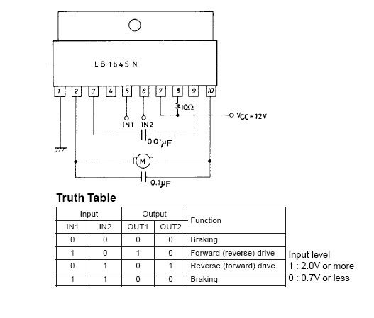
The LB1645 motor driver chip.
Steve G.
Steve G.
Re: Motor Reverser
sghioto- That ought to work great! Cheap chip, and super simple!
I'll order some today!
Thanks very much!
John
I'll order some today!
Thanks very much!
John
WA2RBA
Re: Motor Reverser
Found another option at All Electronics ($2)- Rohm BA6886N.
http://www.allelectronics.com/mas_asset ... A6886N.pdf

http://www.allelectronics.com/mas_asset ... A6886N.pdf
WA2RBA
Re: Motor Reverser
Hi jwax. Either IC is worth having on hand, but all your situation needs is two transistors. Connect emittor/sources to ground and the collector/drains to one side of the motor each and the bases/gates to the other side of the motor through a suitable resistor. Now, when V+ is applied to one side the other is grounded through the transistor.
Re: Motor Reverser
Yeah I would like to see that schematic tooInteresting concept Einar, but could you provide a schematic?
A motor reversal circuit will require at least 4 transistors generally called a "H" bridge.
Something like this:
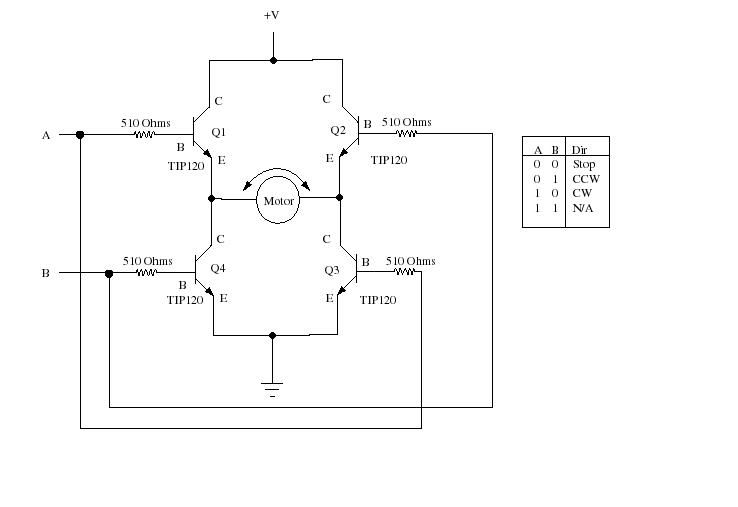
Steve G.
-
dyarker
- Posts: 1920
- Joined: Fri Aug 22, 2003 1:01 am
- Location: Izmir, Turkiye; from Rochester, NY
- Contact:
Re: Motor Reverser
In first post he said he had two supplies, though he didn't say one was positive and one negative. If he has both polarities, two transistors will do.
Cheers,
Cheers,
Dale Y

Re: Motor Reverser
Actually, It doesn't matter if the supplies are positive or negative as long as they don't sharedyarker wrote:In first post he said he had two supplies, though he didn't say one was positive and one negative. If he has both polarities, two transistors will do.
Cheers,
a common ground to themselves. Just hook them up like batteries in series with the motor ground
in the middle, use a SPDT (or 1/2 a DPDT) switch with the remaining Pos and Neg from the PS's
to the outside of the switch and the pos from the motor hooked to the switch center. You can
use 2 transistors to do this also, replacing each half of the switch. Ultimately the easiest way
as far as I can see, IF the PS's allow it.
CeaSaR
Hey, what do I know?
Re: Motor Reverser
Both 12 volt supplies share a common ground. When one is +12, the other is floating.
The motor is to turn CW when wire A goes +12, and CCW when wire B goes +12.
With both A and B are OFF, motor is stopped. A and B are never both ON.
Seems the four transistor approach of Steve G. (sghioto) ought to do it.
The motor is to turn CW when wire A goes +12, and CCW when wire B goes +12.
With both A and B are OFF, motor is stopped. A and B are never both ON.
Seems the four transistor approach of Steve G. (sghioto) ought to do it.
WA2RBA
Re: Motor Reverser
Yeah, the H bridge is probably the best for a single polarity supply.
Plus, you'll only need one of them (supply, that is).
CeaSaR
Plus, you'll only need one of them (supply, that is).
CeaSaR
Hey, what do I know?
Re: Motor Reverser
I have drawn up the circuit I described earlier. The circuit Steve gives is the standard but is not a good choice for the DIY ; it self destructs if both inputs go high. I have included a cicuit that does not do this as well. Go to Photobucket.com enter Einarscircuits and look for motor drivers.
Re: Motor Reverser
That's an intriguing circuit Einar M! What is the function of the zeners? Reverse spike protection?
WA2RBA
Who is online
Users browsing this forum: No registered users and 144 guests