Check to see if pin 5 (the input pin) can "float". If it is like digital signals, if you let it float (i.e. not connected) it will pick up stray voltage and go nuts. Chances are it should be connected to something. for a simple test, make a voltage divider (2 same resistance resistors). Hook the two resistors together (in series). So you will have one end of each resistor unconnected. Take one of those ends and hook it to Vcc. Take the other end and hook it to ground. In the middle (the joint where the two resistors meet) you will see 1/2 the input voltage. Hook this to the input in and see if the graph goes half way...
Note that I have just read the thread and I didn't look at any of the datasheets mentioned - or the schematics for that matter. It is just an idea from someone who has dealt with floating pin problems in the past...
// Typed in a huge hurry
Hope it helps,
Kevin
lm3919?
Re: lm3919?
goner19,
Pin 5 connects to the output of your sensor/circuit. You can't just leave it open and expect the circuit to function with no input signal. To test the LM3914 connect the 5 volts across a 10K pot and connect the wiper leg to pin 5. Looking at the PDF datasheet change R1 to 1K and R2 to 4.7K. Using the same 5 volt supply for the chip and the LEDs and with the resistor values as chosen should turn #1 LED on at about .39 volts and the #10 LED at 3.9 volts.
Steve G.
Re: lm3919?
kevin..you are my guru!!!
ill try that now....
ill try that now....
Re: lm3919?
hey psycho i did what you said with two 100k resistors..
i must be hella dumb cuz my voltage divider only causes .2 drop (in the middle of the 2 resistors) from the 5.2v im putting into it. and the ground side and the positive sides both have 5.2. do i need to use bigger resistors?
i did what you said also sghioto
but the 10k pot only acts as a dimmer for all the leds...
the trouble shooting page of the buckeye schmatic says i should have 1.25v at pin7 which he is calling the "input pin" but i think that is the referance out pin and he ment pin5 which should be the input pin.
my pin5 has the full 5.2v and my pin7 has 4.42v
would a bigger pot help here? a resistor before the pot to pin5?
thanks again guys
Re: lm3919?
i just put in 2 480k resistors between the pot and pin 5
i can get pin 5 down to 2.82v....
but the hertzburg princepal kicks in where just testing turns the leds off
do i now need to adjust the resistors at pin 6,7,8?
i can get pin 5 down to 2.82v....
but the hertzburg princepal kicks in where just testing turns the leds off
do i now need to adjust the resistors at pin 6,7,8?
Re: lm3919?
If you are working on a breadboard, plug one end of one resistor into Vcc. Plug one end of another (same resistance) resistance into ground. connect the free ends of the resistors together. Use a meter and put the black probe to ground and the red probe on the junction of the two resistors and you should have roughly 1/2 the voltage.
Start with the above - don't connect ANYTHING except the two resistors and the meter. See if you get the divider to work correctly. If the resistors were EXACTLY equal, it would divide the voltage in half. But, since the resistors have tolerance (5%, 10%, etc) the voltage may not be exactly 1/2 of the input voltage. If you did it right, this will prove to you that a voltage divider works. Use 1k resistors or more.
When you say the ground side has 5.2 volts, that is impossible. You must not have it hooked up correctly. If the ground side is hooked up to the negative lead of the meter and the red lead is hooked to ground, there can be no voltage difference because they are both ground.
You have the negative side of the voltage divider hooked up to something other than ground...
Re: lm3919?
Once you have the voltage divider working, take the center tap and hook it to the input of your circuit.
All a POT is is a voltage divider. By turning the knob, you change the ratio of the resistance of the pot. Think of it like two variable resistors with a tap in the center. One leg goes to ground, one leg goes to Vcc and one leg is the output voltage(wiper)... Sounds familiar, huh? The wiper is the "center" of the voltage divider you made above. So if you have a 10K pot and it is "centered", the wiper will be dividing the voltage in half. There are calculations you can make to KNOW what voltage and current will come out of your divider. You can also use a POT as a variable current limiting resistor, but you are going to use it as a voltage divider(all 3 pins).
Kevin
Re: lm3919?
i soildered the 2 100k resistors together
i stuck one end in the + and one into the - on my breadboard
i then took the voltage in the 3 open spaces...but i did still have all the leds and the 3914 all on the same board
ill try again on a differant board w nothing else..
i was just using 2 pins on the pot....i know that usually one leg of the pot is doubled back on itself...
the values on the buckeye diagram are way low like in the millavolt range could this be part of my trouble?
thanks again...wish i could up load video...
Re: lm3919?
The size of the resistor on pin 7 controls the brightness of the LEDs (current limiting resistor).
If you have a breadboard, plug the two resistors in and make the divider - that way you will understand how they work and how to test them.
The way the guy is using the chips is more complex than you should be testing with. Get yourself a breadboard (Radio-Shaft has em). Setup the circuit in the datasheet. Make sure it works and you understand how it works. Then move on to the more complex circuit.
Re: lm3919?
Oh, and are you still getting a voltage reading on the negative side of the voltage divider??? If you are then you do not have it connected to a proper ground - there must be some resistance between it and ground.
Re: lm3919?
i get it kevin
it seemed to me that the data sheet was more complex than what the buckeye dude was doing...
do you say that cuz he is running two lm3914s?
i got bread boards up the wazoo..
i even got this cool aluminium one that costs 100$
ill re do the divider in the am....
one thing for sure by the time i work this out i should have a pretty good handle on 3914...
Re: lm3919?
ok i just hooked my power supply straight to the divder and yup it worked...
half voltage in the middle....
half voltage in the middle....
Re: lm3919?
goner19,
Steve G.
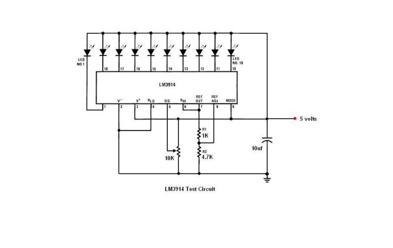
Doesn't sound like you have the pot connected correctly from that comment. Just to set the record straight here's how the test circuit should be connected and running off a 5 volt supply.i did what you said also sghioto
but the 10k pot only acts as a dimmer for all the leds...
Steve G.
Re: lm3919?
wow steve thats a whole differant schematic than i am looking at
but youre right the pot was not hooked up right.
mine was just going from the 5v+ to the pin 5
i will try it again w a ground conncetion added
there are a lot of differant ways to get this chip to do the same thing...interesting
thanks
but youre right the pot was not hooked up right.
mine was just going from the 5v+ to the pin 5
i will try it again w a ground conncetion added
there are a lot of differant ways to get this chip to do the same thing...interesting
thanks

Re: lm3919?
Aha! You were feeding the full amount of "signal" to the input, but only varying the amount of current going in.
In order to use the VR as a full voltage divider, you should have 2 different potentials (voltages) at either end.
In your case, +5 V and GND (0 V). That way you can vary between the 2 to get the range you want.
Perhaps you could post your schematic/photo of the board so that "we" (the members of the board) can actually
double check the wiring. Sometimes it is easy to miss something by 1 pin or insert something backwards, etc.
A fresh set of eyes may pick up such things.
CeaSaR
Hey, what do I know?
Who is online
Users browsing this forum: No registered users and 67 guests