i have the white small breadboard but not sure how to traslate from the breadboard used on top to the one used on the bottom...
is it like this:
http://img706.imageshack.us/img706/1409/54492389.jpg
Breadboard question
-
SuperMiguel
- Posts: 20
- Joined: Mon Jan 04, 2010 12:03 pm
- Contact:
-
SuperMiguel
- Posts: 20
- Joined: Mon Jan 04, 2010 12:03 pm
- Contact:
Re: Breadboard question
or i will have to use this http://www.adafruit.com/index.php?main_ ... ucts_id=51 with that small breadboard??
-
SuperMiguel
- Posts: 20
- Joined: Mon Jan 04, 2010 12:03 pm
- Contact:
Re: Breadboard question
i also found this: http://www.ladyada.net/images/arduino/b ... red1_t.jpg but why there is no ground cable?

Re: Breadboard question
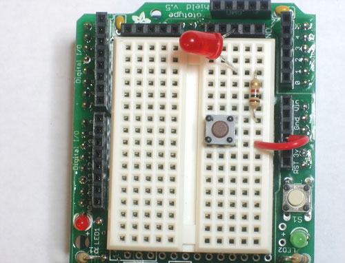
The top breadboard (bb) has a set of power "rails" at the top and bottom, ie, the first row is positive (+V)
and the second row is negative (-V or GND). This is carried over to the bottom set of power rails by the
jumpers at the far right. The rest of the holes are set up in columns separated by the depression in the
center of the board.
In the second board, there are no power rails, only columns as explained above. Consequently, the +5 and
GND are shown shorted together.
The best way to visualize how the boards are layed out is to look at this wiki on breadboards. At the bottom
of the 1st section on the right, you'll see a protoboard layout. This is a great example of how the connection
strips are oriented (minus the center strip). Further down is an explanation of a typical bb layout.
Looking at the small bb you reference in your first link, it is similar to the protoboard I pointed out in the wiki,
except without the horizontal busses.
I hope I explained it well enough for you to understand.
CeaSaR
Hey, what do I know?
-
angelinajelly24
- Posts: 2
- Joined: Tue Dec 08, 2009 4:01 pm
- Contact:
Re: Breadboard questionhttp://www.practicebuilding
A breadboard (protoboard) is a construction base for a one-of-a-kind electronic circuit, a prototype. In modern times the term is commonly used to refer to a particular type of breadboard, the solderless breadboard (plugboard).
Because the solderless breadboard does not require soldering, it is reusable, and thus can be used for temporary prototypes and experimenting with circuit design more easily. Other, often historic, breadboard types don't have this property. This is also in contrast to stripboard (veroboard) and similar prototyping printed circuit boards, which are used to build more permanent soldered prototypes or one-offs, and cannot easily be reused. A variety of electronic systems may be prototyped by using breadboards, from small analog and digital circuits to complete central processing units.
Because the solderless breadboard does not require soldering, it is reusable, and thus can be used for temporary prototypes and experimenting with circuit design more easily. Other, often historic, breadboard types don't have this property. This is also in contrast to stripboard (veroboard) and similar prototyping printed circuit boards, which are used to build more permanent soldered prototypes or one-offs, and cannot easily be reused. A variety of electronic systems may be prototyped by using breadboards, from small analog and digital circuits to complete central processing units.
Who is online
Users browsing this forum: No registered users and 56 guests