Signal Tracer revisited.......
-
Robert Reed
- Posts: 2277
- Joined: Wed Nov 24, 2004 1:01 am
- Location: ASHTABULA,OHIO
- Contact:
Re: Signal Tracer revisited.......
3V Square or 4V Tri would have close to the same rms power. How are you coupling either device to the circuit?
-
Janitor Tzap

- Posts: 1708
- Joined: Sat Aug 12, 2006 5:17 pm
- Contact:
Re: Signal Tracer revisited.......
There is no physical connection.Robert Reed wrote:3V Square or 4V Tri would have close to the same rms power. How are you coupling either device to the circuit?
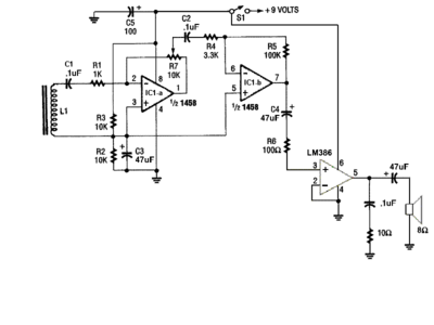
L1 picks up the RF Signal from the signal injectors Inductively.
{Please look at Schematic.}
Signed: Janitor Tzap
-
Robert Reed
- Posts: 2277
- Joined: Wed Nov 24, 2004 1:01 am
- Location: ASHTABULA,OHIO
- Contact:
Re: Signal Tracer revisited.......
Right, the circuit's sensing point is quite clear, but it still doesn't tell me about injectors coupling- i.e.- a probe waved in front of the loop stick, a wire loop on the end of that probe, or the circuits loop stick walking over different circuits in the injectors -what? If the scenarios were identical then there should be very little difference in pickup power.Some thing has to be drastically different in the coupling mode and that sure isn't the freq. difference (800/1000 Hz)
-
Janitor Tzap
- Posts: 1708
- Joined: Sat Aug 12, 2006 5:17 pm
- Contact:
Re: Signal Tracer revisited.......
Here is the Tone generator.Robert Reed wrote:Right, the circuit's sensing point is quite clear, but it still doesn't tell me about injectors coupling- i.e.- a probe waved in front of the loop stick, a wire loop on the end of that probe, or the circuits loop stick walking over different circuits in the injectors -what? If the scenarios were identical then there should be very little difference in pickup power.Some thing has to be drastically different in the coupling mode and that sure isn't the freq. difference (800/1000 Hz)

This is my 1Khz Signal injector.


Thou, my ground wire is coming out of the front near the probe point.
That help?
Signed: Janitor Tzap
-
Robert Reed
- Posts: 2277
- Joined: Wed Nov 24, 2004 1:01 am
- Location: ASHTABULA,OHIO
- Contact:
Re: Signal Tracer revisited.......
Your circuit has an inductive pickup and the probes (apparently) have no current flowing thru them to create a magnetic field. Could you wind several turns of wire into a coil and place them in series with a 1K resistor, then attach it to your probes one at a time and see if that makes a difference? Even though they are they are both open circuits and one did work,I am curious about that.
Re: Signal Tracer revisited.......
That M77 tracer looks similiar to the wire tracers I've used for alarm wiring. If I remember correctly the tone signal is modulated on a low frequency carrier wave maybe 100KHz. The pickup device was basically a radio receiver with a demodulator circuit to detect the tone. Point is the audio tone level is way too low to detect using your circuit.
Steve G.
Steve G.
-
Robert Reed
- Posts: 2277
- Joined: Wed Nov 24, 2004 1:01 am
- Location: ASHTABULA,OHIO
- Contact:
Re: Signal Tracer revisited.......
Sighioto
I was thinking along the same lines, but the fly in the ointment here is that he picked up the triangular wave but not the square wave. The square wave is much richer in harmonics reaching higher in the frequency spectrum so that signals a loopstick is normally accustom to should be present. The tri-wave would not have nearly as strong signals in the upper frequencie bands.
Yet it picked up the tri-wave signal only.
Jan
one thought regarding your two signal injectors - If you probed the M77 at the ends of its test leads, it looks like you may have been 12"? away from its box. When probing the black plastic injector, you had to be very near its box due to a box mounted tip. Its possible that the black one worked because of the probes (loopstick) proximity to the actual current carrying circuits within the box and in reality picked up thase signals.

Re: Signal Tracer revisited.......
A long time a go when my family moved into a new house, my dad needed to find the end of the doorbell wires hidded underneath the finished walls somewhere. He borrowed an astable square wave multivibrator that I had built. It was just a two transistor oscillating flip-flop with a 9V p-p output. Square waves are rich in harmonics so the signal would be audible in the AM band. He attached the output to the doorbell wires in the basement. He used a regular AM transistor radio to find the other end of the wire upstairs in the hallway. The signal was modulating all over the AM band.Robert Reed wrote: I was thinking along the same lines, but the fly in the ointment here is that he picked up the triangular wave but not the square wave. The square wave is much richer in harmonics reaching higher in the frequency spectrum so that signals a loopstick is normally accustom to should be present. The tri-wave would not have nearly as strong signals in the upper frequencie bands. Yet it picked up the tri-wave signal only.
So Janitor, you still might have some use for that cheap scrap radio.
If you need an inductive pickup for a different project, I wonder if one of those old inductive telephone pickups with the suction cup would work? They don't work on modern telephones, but I've seen them still for sale here and there. I've heard that they pick up TV horizontal sync quite well.
-=VA7KOR=- My solar system includes Pluto.
Re: Signal Tracer revisited.......
The inclusion of the modular phone cord suggests this isn't an RF output device. There's a 1-page "manual"
here -> http://www.lashen.com/vendors/tempo/Man ... 77a77m.pdf
My "M77 Tracer" search returned lots of artillery sites.
here -> http://www.lashen.com/vendors/tempo/Man ... 77a77m.pdf
My "M77 Tracer" search returned lots of artillery sites.
-
Janitor Tzap
- Posts: 1708
- Joined: Sat Aug 12, 2006 5:17 pm
- Contact:
Re: Signal Tracer revisited.......
Ok,
I did another simple test with my HEATHKIT Bench Signal Tracer: Model IT-5283.
I first tried the M77 Tracer with it.
When I got the HEATHKIT'S probe about 6 inches from the RED Wire.
I could pickup the 800Hz Tone.
I then did the same with the 1Khz Signal Injector.
The HEATHKIT Bench Signal Tracer picked up the 1Khz at the same distance.
This leads me to believe that MrAl maybe right.
In that .1uF Caps in the circuit are lessening the amplitude for low frequencies.
I haven't gotten time to try replacing them yet.
But I'll report my finding as soon as I do.
Thanks again.
Signed: Janitor Tzap
-
Janitor Tzap
- Posts: 1708
- Joined: Sat Aug 12, 2006 5:17 pm
- Contact:
Re: Signal Tracer revisited.......
Update:
Well,
I substituted the .1uF for 1uF Tantalum capacitors.
But this only showed little improvement.
Now if I hold the pickup coil next to the case of the M77 Tracer.
I can hear the tone, but not on the red injector wire.
I went back and looked at the original circuit requirements.
The ferrite rod is 1 1/4" inch in length, by 1/4" inch diameter.
The ferrite rod I got from the radio is 1 5/8" inch in length, by 1/4" inch, by 1/8" inch.
#30 Enamel coated copper wire.
I used; AWG #30 Enamel coated copper magnetic wire.
The number of turns is to be 80 to 100 turns.
I only went 80 turns, because I quickly ran out of space on the rod.
I wonder.....
Should I have over lapped the first coil rapping, by just winding back over the first one.
By doing this, would this increase the sensitivity of the coil?
Signed: Janitor Tzap
-
dyarker
- Posts: 1917
- Joined: Fri Aug 22, 2003 1:01 am
- Location: Izmir, Turkiye; from Rochester, NY
- Contact:
Re: Signal Tracer revisited.......
The ferrite the rods are made of is different. Even if the rods were exactly the same size, a rod intended for AM radio isn't going to work well at 800Hz/1KHz.
Cheers,
Cheers,
Dale Y
Who is online
Users browsing this forum: No registered users and 38 guests