Greetings Craig,
Craig Kendrick Sellen wrote:
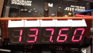
See attachment circuit.
Is there any way this circuit can be modified to a 3 digit frequency counter? I realized the software will have to be changed. But if someone out there can do this it will be much appreaced. I also realized that the D1, Q3, RLY1 can be omited. :smile:
The circuit is not a frequency counter, but it does have
the bare structure for one (uC, displays, user switches).
To expand it to a third digit would require one more
display and a dedicated low-side driver transistor for
it. Unfortunately, there are no spare pins on the uC.
A work around would be to encode the two existing pins
and add a decoder IC (two bit binary decoder).
By using a larger uC (with more IO pins) all the
external ICs can be removed (only one transistor
per digit would remain, plus some Rs and Cs and
switches). A crystal timebase would be superior.
Take a look at the cover story in Nov 2007 Nuts
and Volts for a similar uC and display solution.
What frequency range do you need?
What precision do you need?
Comments Welcome!