Assistance required for circuit design

This is the place for any magazine-related discussions that don't fit in any of the column discussion boards below.
Post Reply
Zaaka72
Posts: 5
Joined: Thu Nov 02, 2023 7:53 pm
Contact:

Assistance required for circuit design

Post by Zaaka72 »

Good Morning all,
I am looking for somebody knowledgabe to assist in the initial design of a circuit, I have an E-Bike with acontroller that does not have a High-Brake level, so cannot power a brake/stop light.

as i believe the brakes have a 5v constant current and when the brake is pulled it drops to 0v, I am looking for a circuit that would detect the drop in voltage and trip a relay that would switch a 12v supply on to power the brake light, I have a basic idea, drawing attached but dont know how to get started designing the circuit. Would any of you guys ave and advice or examples i could take on board?Image
dyarker
Posts: 1920
Joined: Fri Aug 22, 2003 1:01 am
Location: Izmir, Turkiye; from Rochester, NY
Contact:

Re: Assistance required for circuit design

Post by dyarker »

5V and 12V are voltages.
Current is measured in Amperes (A) or milliAmperes (mA)

How much current does the 12V load need?

How much current can brake spare for the control circuit?

It could be two transistors and two resistors.

Or, a relay with 5V coil and use the NC (normally closed) contacts for the 12V load.
((if coil is not powered (0V), which is "normal", the NC contacts are connected.
When the coil is powered the NO (normally open) contacts are connected.))
Dale Y
Zaaka72
Posts: 5
Joined: Thu Nov 02, 2023 7:53 pm
Contact:

Re: Assistance required for circuit design

Post by Zaaka72 »

thankyou for replying, I have included this youtube link to show you what the situation is, bare in mind that my controlled DOES NOT have a High Brake line, so I have a separate 12v supply that powers all bikes lights, indicators etc and I have a 12v LED brake light. all lights are LED.

Video link is here: https://youtu.be/zgJAY_0xSTM?si=kR6jHNzjOmgGH-O3

Its night time here now will post 12v wattage etc in the morning.
dyarker
Posts: 1920
Joined: Fri Aug 22, 2003 1:01 am
Location: Izmir, Turkiye; from Rochester, NY
Contact:

Re: Assistance required for circuit design

Post by dyarker »

Bike frame is common for both though?

Easier if bulb socket is not connected to frame.
Dale Y
Zaaka72
Posts: 5
Joined: Thu Nov 02, 2023 7:53 pm
Contact:

Re: Assistance required for circuit design

Post by Zaaka72 »

I dont have a common frame, just a separate earth/common wire, the 12v is at 210w
Zaaka72
Posts: 5
Joined: Thu Nov 02, 2023 7:53 pm
Contact:

Re: Assistance required for circuit design

Post by Zaaka72 »

here is a block diagram of what I have, the box in bold is what I am trying to develop.
Image
dyarker
Posts: 1920
Joined: Fri Aug 22, 2003 1:01 am
Location: Izmir, Turkiye; from Rochester, NY
Contact:

Re: Assistance required for circuit design

Post by dyarker »

I take it you want brake light from lo brake?
NV_LED.png
NV_LED.png (4.18 KiB) Viewed 32740 times
If you have individual LEDs I need more info to calculate R-Limit. If the brake light is an assembly rated 12V then R-Limit is built in, we don't need a separate R-Limit.

Still need the current rating of the brake light to calculate RQ.

Cheers,
Dale Y
dyarker
Posts: 1920
Joined: Fri Aug 22, 2003 1:01 am
Location: Izmir, Turkiye; from Rochester, NY
Contact:

Re: Assistance required for circuit design

Post by dyarker »

How it works:

Q1 is PNP, it is on when base is more negative than emitter. Q2 is NPN, it is on when base is more positive than emitter. On is collector/emitter current caused by a smaller base current when base/emitter is forward biased (as in first two sentences).

Q2 switches the LED current. To keep it cool, and not waste power, Q2 should saturate (fully on) at a bit more current than the LEDs will pass to guarantee statuation. If saturation occured at less the LEDs would be dim.

To do this Q2's base current must be the collector (where the LEDs are) current divided by tha gain (hfe) of Q2. This current is controlled by RQ at Q1's emitter. Q1's base current is limited by the emitter resistance times Q1's gain.

Off sequence:
Q1 base and RQ voltage both at +5V, so no current and no collector current. Means no Q2 base current, so no Q2 collector/emitter current; LEDs dark.

On sequence:
0V on Q1 base causes a small current in base, causing a larger current Q1 emitter to collector Q2 base and emitter, and still larger current Q2's emitter and collector and the LEDs emit light.

With LED current I can suggest transistors, look up their gains and calculate RQ.
Dale Y
Zaaka72
Posts: 5
Joined: Thu Nov 02, 2023 7:53 pm
Contact:

Re: Assistance required for circuit design

Post by Zaaka72 »

I think I may have to go down the relay option as I sometimes have a trailer on the bike with extra tail/brake light and indicators all running off the 12v system. I have a manual switch in place that works but cant be using a switch all the time when braking as it is unsafe.

these are the brake/tail lights I am using

Specifications:
Lens Color: PMMA Lens and ABS housing
Rate Voltage: 12V
Working voltage: 12-15V
Rate Wattage: 5W
Diameter: 89mmx35mm

https://www.ebay.co.uk/itm/304268251187 ... R4bXmJj2Yg

I have updated the block diagram to include the trailer hitch
Image
dyarker
Posts: 1920
Joined: Fri Aug 22, 2003 1:01 am
Location: Izmir, Turkiye; from Rochester, NY
Contact:

Re: Assistance required for circuit design

Post by dyarker »

5W / 12V = 0.416A (seemed like a lot of current for LEDs till I looked at the ad for the light you're using)

Instead of one high power transistor for Q2, I'll 2 smaller ones. One for bike and one for trailer. (It will okay if trailer is not plugged in.)

I will redo the schematic, do the calculations, and get back to you later today (my time zone's today).
Dale Y
dyarker
Posts: 1920
Joined: Fri Aug 22, 2003 1:01 am
Location: Izmir, Turkiye; from Rochester, NY
Contact:

Re: Assistance required for circuit design

Post by dyarker »

Q2 and Q3 are 2N2222A. In TO-18 package. They are 600 mA maximum current and 1.8 W maximum heat disipation at 25°C.

At 417 mA, VSAT is 1V = 0.417W. Assuming the circuit will be in an enclosure, and you'll ride on warm days the transistor temperature will be higher; the maximum dissipation must be derated. TO-18 heat sinks cost more than the 2N2222As, but ensure better cooling. They look like:
TO18HeatSink.png
TO18HeatSink.png (6.22 KiB) Viewed 32297 times
Minimum gain of 2N2222 at 150 mA is 100, at 500 mA is 40. For our 417 mA I'll call it 45. Making the resistors the next lower standard will ensure saturation. R2 and R3 may not be necessary, but will compensate for different gains of Q2 and Q3, and actual current of LED assemblies.
So current in each of R2 and R3 will be:
417 mA / 45 = 9.3 mA

Current in R1 with trailer connected:
9.3 mA * 2 = 18.6 mA

Resistors R2 and R3:
1 V / 9.3 mA = 107.5 Ω. Standard value for R2 and R3 = 100 Ω.
1 V * 10 mA = 0.01 W. 1/8 W or larger is okay. (or even smaller, but SMD is hard to work with by hand)

Worst case VBE of 2N2222a is 1.2 V, and VCE of 2N3906 (suggested Q1) is 0.4V, 1 V of R2 and R3.
Voltage across R1:
5 V - 1.2 V - 1 V - 0.4V = 2.4 V

Resistor R1:
2.4 V / 18.6 mA = 129.03V. Standard value for R1 = 120 Ω.
2.4 V * 18.6 mA = 0.045W. 1/8 W again okay.

(For closer calculations the base/emitter current would be added to the collector/emitter current. I considered insignificant compared to the reductions to standard resistor values.)

Q1 base current:
18.6 mA / 75 = 248 μA. Should be insignificant to the controller.
NV_LED.png
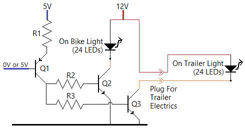
NV_LED.png (9.21 KiB) Viewed 32297 times
Dale Y
dyarker
Posts: 1920
Joined: Fri Aug 22, 2003 1:01 am
Location: Izmir, Turkiye; from Rochester, NY
Contact:

Re: Assistance required for circuit design

Post by dyarker »

1. DC electronics is basically simple algebra and knowing when to use which formula.
2. Semiconductors add some more rules, but still not too hard for ON/OFF.
3. DC with capacitors and inductors brings in curves, but still algebra.
4. Next step would be linear/analog AC like audio amplifiers.
5. AC including capacitors and inductors adds imaginary numbers. (I got through college; don't ask me to do it now!)

Digital circuits/logic takes different thinking pattern, is an extension of 2. (Unless you're designing gigaHertz logic boards where a 1 inch connection is a transmission line and you're in 5. territory again.)

Just don't dive in too deep for a first project.
Dale Y
Post Reply

Who is online

Users browsing this forum: No registered users and 23 guests