Hi all!
I'm new to this forum (and to electronics), so I apologize if this question has been asked before. I'm not sure what you would call this type of circuit, so I wasn't sure what to search for.
I've built a very simple alarm clock using a PIC18F4550, with a 4-digit LED display using multiplexing, and a piezo buzzer for the alarm. I'm using an 7805 voltage regulator to bring 9V down to 5V (though I'm sure there are much better options).
What I want to do is add a 9V battery back-up so that I can run the clock off of either a wall-wart transformer or the battery, in case the power goes out. I'd like to connect part of the circuit to a pin on the 4550, so that I can "sense" whether the battery is being used or not (if it is, I'd like to reduce the duty cycle of the LEDs via programming).
Can someone suggest a circuit to do this? I was thinking of using a MOSFET but I couldn't get the circuit exactly right.
Thanks!
Steve
Circuit Question

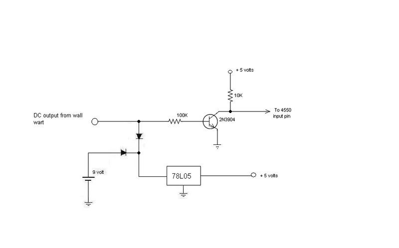
I thought I still had the schematic for the attached circuit including when I had power sense to it.
There are a number of ways you can sense the voltage, the simplest and least amount of ocde reuired would be to have a resistive divider across whichever dc supply you are measuring. Dimension the resistors such that the Pic will see a 'low' once the supply voltage has gone below the value you require. The code then just has to poll that pin and you can check from a high to low and whatever you need.
If you want a more intelligent or want to track the voltage then using the divider just to keep the voltage in range of the chips ADC inputs, you can get a real reading of the voltage at all times.
Colin
On a clear disk you can seek forever.
Ahh, it took me a moment to get what you were saying. To clarify, I just added a single "status indicator" LED to show whether the clock was running on battery or outlet power.
I had planned to just lower the duty cycle on the clock display when running on battery, however, your suggestion makes a lot of sense since the LED display is probably sucking the most current out of the circuit: I could completely turn off the display when on battery power, and use momentary PB to show the time when needed. I want to make this a portable clock, but I still may add this as an option. Great idea-- thanks!
Steve
Who is online
Users browsing this forum: Ahrefs [Bot] and 1 guest