12Vdc Fan Speed Controller.........

This is the place for any magazine-related discussions that don't fit in any of the column discussion boards below.
User avatar
Janitor Tzap
Posts: 1709
Joined: Sat Aug 12, 2006 5:17 pm
Contact:

Re: 12Vdc Fan Speed Controller.........

Post by Janitor Tzap »

Axeman Surplus Comes Through Again!

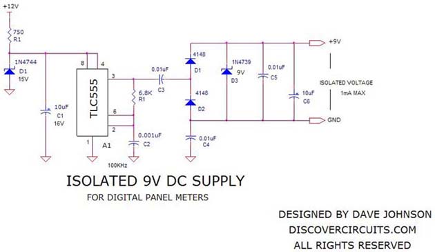
I checked around with several TV shops that were still around my area for the resistor.
{Nothing.} :sad:

So, I gave Axeman Surplus a call.
Turns out one of the large electronic parts suppliers in the cities shuttered it's doors,
and Axeman bought out the whole stores inventory. :grin:

Thus,
when I called them, on the off chance they would have the resistor I needed.
The clerk said he had a bin of 200 pieces.
He was getting 0.10 cents a resistor.
I asked him too put 10 a side for me, and I'd make the long trek to the cities in a few days.

I'll combine multiple stops into the cities.
Thus, making going down to the cities for just the resistors worth while. :smile:


Signed: Janitor Tzap
User avatar
Lenp
Posts: 1529
Joined: Thu Oct 26, 2006 8:11 pm
Location: Maryland
Contact:

Re: 12Vdc Fan Speed Controller.........

Post by Lenp »

Flash from the past...

I can remember years ago, when insulated carbon resistors, no not carbon film, were in vogue, if some odd value, say for a meter calibration was needed, you would just make it.

Simply get a carbon resistor, higher in wattage but lower in resistance value than needed. Clamp it snugly it in a vise and connect the resistor to your ohmmeter or bridge, if you're that fortunate. Then with a fine file start filing a groove across the resistor's diameter near its center. Soon you would get through the insulation and into the resistance element. Each file stroke removed a bit of the resistance core and the resistance increased. When the value desired was obtained, the groove was sealed with something like red glyptol to prevent moisture, and it was a done deal. The resistor wattage was increased only to provide more physical strength after the cut weakened the resistor body.

I have a fluke IR thermometer. Inside the battery compartment through a couple of holes you can see what appears to be film resistors on the circuit board. No doubt they were laser trimmed, for calibration after assembly. I guess there's really nothing new under the sun!

:idea: If you find some of the old insulated resistors, give it a try! It's really not a bad flash back time waster!
Len

“To invent, you need a good imagination and a big pile of junk.” (T. Edison)
"I must be on the way to success since I already have the junk". (Me)
User avatar
Janitor Tzap
Posts: 1709
Joined: Sat Aug 12, 2006 5:17 pm
Contact:

Re: 12Vdc Fan Speed Controller.........

Post by Janitor Tzap »

Lenp wrote:Flash from the past...

I can remember years ago, when insulated carbon resistors, no not carbon film, were in vogue, if some odd value, say for a meter calibration was needed, you would just make it.

Simply get a carbon resistor, higher in wattage but lower in resistance value than needed. Clamp it snugly it in a vise and connect the resistor to your ohmmeter or bridge, if you're that fortunate. Then with a fine file start filing a groove across the resistor's diameter near its center. Soon you would get through the insulation and into the resistance element. Each file stroke removed a bit of the resistance core and the resistance increased. When the value desired was obtained, the groove was sealed with something like red glyptol to prevent moisture, and it was a done deal. The resistor wattage was increased only to provide more physical strength after the cut weakened the resistor body.

I have a fluke IR thermometer. Inside the battery compartment through a couple of holes you can see what appears to be film resistors on the circuit board. No doubt they were laser trimmed, for calibration after assembly. I guess there's really nothing new under the sun!

:idea: If you find some of the old insulated resistors, give it a try! It's really not a bad flash back time waster!
:lol: :lol: :lol:
Well, I did that too, with very limited success. :lol:
I guess I didn't have very much patience then.
Ruined a lot of resistors by filing just a bit too much carbon. :P


Signed: Janitor Tzap
User avatar
Lenp
Posts: 1529
Joined: Thu Oct 26, 2006 8:11 pm
Location: Maryland
Contact:

Re: 12Vdc Fan Speed Controller.........

Post by Lenp »

"Ruined a lot of resistors by filing just a bit too much carbon."
Probably a resistor just under the value needed would have taken less filing and the higher wattage would provide more strength.
I always used a vise so the resistor didn't twist. Even at that, there were a few failures, but those resistors were pretty cheap.
Len

“To invent, you need a good imagination and a big pile of junk.” (T. Edison)
"I must be on the way to success since I already have the junk". (Me)
User avatar
Janitor Tzap
Posts: 1709
Joined: Sat Aug 12, 2006 5:17 pm
Contact:

Re: 12Vdc Fan Speed Controller.........

Post by Janitor Tzap »

UPDATE:

ARGH!!!!!
{Pounds head on work bench}

After finally getting the right resistor for the Isolated 9Vdc Supply.
Image
The output is to low, when I connect the panel meter to it.
Unloaded 9.1Vdc
Loaded 4.1Vdc.
Image
Image
Red
Black
Blue
Yellow
Red & Black are the 8Vdc to 12Vdc Power input.
Blue & Yellow are the test leads.
Yellow is Positive.
Blue is Negative.
Uses the ISL7106 CM44
Anyone got a better circuit?
Or how I can modify this one to up the current?


Signed: Janitor Tzap
User avatar
Janitor Tzap
Posts: 1709
Joined: Sat Aug 12, 2006 5:17 pm
Contact:

Re: 12Vdc Fan Speed Controller.........

Post by Janitor Tzap »

UPDATE:

After I accidently power up the Panel Meter with Voltage leads reversed,
and the Panel Meter powered on like nothing was wrong.

I looked at wiring it with just three wires.
Red +12V Power
Black -12V Power
Yellow +Test Input to the +12V.

It worked! :shock:

I then tried it with:
Red +12V Power
Blue -Test Input to -12V Power
Yellow +Test Input to the +12V.

That worked! :shock:

Red +12V Power
I then tied the Black & Blue Wires together, and went to the -12V Power.
Yellow +Test Input to the +12V.

That also worked! :shock:

Why the h*ll couldn't YB Electronics tell me this was how you can connect it up.
This is probably why it was only $5.99.
They didn't want to take the time printing up wiring diagrams for them.
:x

Yes Lenp, go ahead and say it.......


Signed: Janitor Tzap
User avatar
Lenp
Posts: 1529
Joined: Thu Oct 26, 2006 8:11 pm
Location: Maryland
Contact:

Re: 12Vdc Fan Speed Controller.........

Post by Lenp »

Hi JT

Blue & Black wires:
I would check the blue and black wires with a meter, or inspect their connections on the PCB. If they are connected together then the two wires are a convenience to the user and are electrically one and the same. if not, as a minimum, connecting them together may affect the meter operation. At a maximum, it may enable the smoke generator. :shock:

"Yes Lenp, go ahead and say it....."
Well, I really do appreciate your closing invitation to contribute something to this thread, but I am at a total loss as to what you would expect me to say! :???:

But, here's some you can pick from....
Get er Done
In an effort to simplify the complicated don't complicate the simple.
Muntz Law. Cut out parts until it stops working, then put that part back in.
Len

“To invent, you need a good imagination and a big pile of junk.” (T. Edison)
"I must be on the way to success since I already have the junk". (Me)
User avatar
Janitor Tzap
Posts: 1709
Joined: Sat Aug 12, 2006 5:17 pm
Contact:

Re: 12Vdc Fan Speed Controller.........

Post by Janitor Tzap »

Lenp wrote:Hi JT

Blue & Black wires:
I would check the blue and black wires with a meter, or inspect their connections on the PCB. If they are connected together then the two wires are a convenience to the user and are electrically one and the same. if not, as a minimum, connecting them together may affect the meter operation. At a maximum, it may enable the smoke generator. :shock:
I did check the continuity between the Black & Blue wires, and it reads like I have a diode between them.
Remember I did say:
I accidently power up the Panel Meter with Voltage leads reversed,
and the Panel Meter powered on like nothing was wrong.
And because it worked.
I got suspicious that the Panel Meter was setup for Automotive, Motorcycle, or Boat use.
Thus, why tested it in the three wire configuration.
I think I'll wire it up;
Red +12V Power
Black -12V Power
Yellow +Test Input to the Emiter on the TIP121.
Since it doesn't really need the - Blue sense input wire.
Lenp wrote:"Yes Lenp, go ahead and say it....."
Well, I really do appreciate your closing invitation to contribute something to this thread, but I am at a total loss as to what you would expect me to say! :???:

But, here's some you can pick from....
Get er Done
In an effort to simplify the complicated don't complicate the simple.
Muntz Law. Cut out parts until it stops working, then put that part back in.
You worked on Muntz TV's? :shock:
I've only worked on one, when I was going to the local Votech.
But it wasn't just me.
Had the instructors, plus nine other guys messing with it to get the vertical to stop rolling.
Talk about your minimum parts, plus it use parts from several different TV manufacturers. :lol:


Signed: Janitor Tzap
User avatar
Lenp
Posts: 1529
Joined: Thu Oct 26, 2006 8:11 pm
Location: Maryland
Contact:

Re: 12Vdc Fan Speed Controller.........

Post by Lenp »

Actually, if you understand the business model of Muntz, it was pretty effective. Use just enough, and no more.
In those days RCA, Philco and all the other big names made sets with multiple RF and IF stages to assure plenty of gain in the fringe signal areas. So much in fact that the AGC clamped it most of the time. Muntz chopped much of that away, using fewer stages, at less cost. He compensated by limiting the sales to areas in big cities, with high signal levels, so there was no reception problems. The 'bad' name was earned because many rural folks, looking for a good deal, bought these 'big city' sets and used them in fringe areas, where reception problems were common, or moved from a good to poor signal area and took the set with them.
Right, like you said about service issues being common. Since he bought excess inventory from whoever had it and used what he could. I remember seeing a Muntz set with several hole patterns for the power transformer, to accommodate whatever footprint transformer he might be able to get! Service data was often 'close enough' like a generic all American five radio. If you did a lot of service, and hoarded the junkers, they often provided many 'exact replacement' parts! I'll just bet that H.W.Sams had a nightmare with the Photofact drawings and parts recommendations for these sets. Remember that Heathkit started in a similar manner, buying military surplus components, Can you remember all the JAN tubes they first used, and the parts packed a-la military?

I often find when doing a design I put too many bells and whistles in, using the just-in-case theory. The closer I get to the final design much of that is 'Muntzed' since it is really unneeded or unwanted fluff.

I designed a medical device years ago that originally had two digital temp controls with alarms and battery backup, dual vacuum controls and much more in a big expensive cabinet. The present model uses an analog control, no alarms since it inherently will not dangerously overheat and the vacuum system was simplified and put into a streamlined and smaller cabinet. They sell worldwide, do their job well, and make me money, just like 'Madman Muntz'!
Len

“To invent, you need a good imagination and a big pile of junk.” (T. Edison)
"I must be on the way to success since I already have the junk". (Me)
User avatar
Janitor Tzap
Posts: 1709
Joined: Sat Aug 12, 2006 5:17 pm
Contact:

Re: 12Vdc Fan Speed Controller.........

Post by Janitor Tzap »

:lol: :lol: :lol: 'Madman Muntz'!
Yeah, that's what one of the older instructors called him too. :lol:

That Muntz TV drove us nut's.
The components had such loose tolerances, that if the running temp in the case changed enough,
it would throw off settings we had just got done doing.

I've worked on several off brand sets that used parts from different manufacturers.
But they were better matched up components.

I did work on a 19" GE television, {Just after RCA & GE merged}.
It was really an RCA TV.
On the main chassis board was IR pickup for a remote.
Only the case didn't have a window for the IR pickup.
While I had the main chassis board out, fixing the audio section.
I took a Universal Remote, and tried it on the set, too see if the IR circuit was working.
It was.
I told the customer, and asked if he wanted me too put a IR window on the case, and get a Universal Remote for it.
Well, he was more than willing to pay me for the extra work, turning the set into a remote control version. :lol:


Signed: Janitor Tzap
Post Reply

Who is online

Users browsing this forum: No registered users and 53 guests