
Quick question guys.
On the IEC 320 C7 polarized plug/connector, do you know which is hot and which is neutral? (Connector is a figure 8 with a rounded side and a flattened side.)
I've aquired a tape deck and the power cord is missing. I don't want to send off for one before verifying the deck works.
Thanks,
CeaSaR
Hot / neutral?
Hot / neutral?
Hey, what do I know?
-
dyarker
- Posts: 1918
- Joined: Fri Aug 22, 2003 1:01 am
- Location: Izmir, Turkiye; from Rochester, NY
- Contact:
Re: Hot / neutral?
https://en.wikipedia.org/wiki/IEC_60320#C7.2FC8_coupler
says squared side is usually neutral.
There can not be a written standard because a power cord with a round-on-both-sides 8 shaped connector will fit a one-end-squared male either way. Which would defeat the safety features of knowing which is neutral. Hopefully the equipment is double insulated. If it also runs on 220/240VAC it probably is double insulated because European wall outlets aren't polarized either.
I would check case to ground with voltmeter after connecting power before toching with my fingers.
Good luck,
Dale Y

Re: Hot / neutral?
The flat side of the C7P, is neutral. Not that it makes any real difference to the equipment, or your safety, because neither pin should be directly connected to a metal chassis part. This you can easily check with your ohmmeter. With any ungrounded cordset, an accidental power connection to chassis contact is a 50/50 bet whether it will be the neutral or line and since the chassis is ungrounded that risk still exists, polarized cord or not! Some of the clasisic old radios were potential killers though, with a 2 wire unpolarized power cord and one side of the line tied to the chassis! An isolation transformer was not a convenience, but a necessity, when servicing these radios. Today, it's really likely that after the power switch, everything else is isolated by a transformer and with a switch mode system, there still is isolation.
Millions of devices are safely in use with non-polarized two wire cords. Polarization, unlike grounding which makes more sense, only seems to make sense in some cases. A lamp wire should be polarized, since the shell should be connected to the neutral side of the line to prevent shock when changing a lamp. (As a footnote, the UK uses a double contact lamp base so the shell is isolated from the conductors.) Many guitar amps, with two or three wire power cables, still use a DPDT line reversing switch to help eliminate power interference and hum. Why an all plastic wall wart, fully sealed with a transformer output circuit or a plug in CO2 detector uses a polarized plug, completely eludes me except that polarized plugs tend to be more common, thus cheaper!
To test your deck, I would just carefully hook it up, a-la clip leads, or modify a non polarized cable with a deft slice!
Len
“To invent, you need a good imagination and a big pile of junk.” (T. Edison)
"I must be on the way to success since I already have the junk". (Me)
“To invent, you need a good imagination and a big pile of junk.” (T. Edison)
"I must be on the way to success since I already have the junk". (Me)
Re: Hot / neutral?
Just pulled it out of the storage box. It is a Technics RS-TR170 dual cassette deck, maybe from '95, but don't hang your hat on that. Looking at it, I see why the polarized plug - it has two unswitched outlets on the back, both polarized themselves. I think this'll be easy to figure out.
Thanks guys.
CeaSaR
Thanks guys.
CeaSaR
Hey, what do I know?
Re: Hot / neutral?
Well now, that's interesting! I did a continuity check and, from the outside, there is s dead short across the pins / slots. I'll have to look at it, possibly, tomorrow. Got to go back to work.
CeaSaR
CeaSaR
Hey, what do I know?
Re: Hot / neutral?
Hummmm
Here's a few points to investigate...
Is it really zero or just low?
Does it change with the power switch?
Check for shorted MOV'S across the power line
If it is a transformer power supply disconnect the transformer primary and retest.
If there is no transformer look for shorted diodes, transistors or capacitors.
If you want to do power on tests put a 120 V light bulb in series with the power line. 100 Watt is a good start. It saves the three F'S. .Fires, Fuses and Frustration
Dig through the net for a schematic and post the link here for more help.
Len
“To invent, you need a good imagination and a big pile of junk.” (T. Edison)
"I must be on the way to success since I already have the junk". (Me)
“To invent, you need a good imagination and a big pile of junk.” (T. Edison)
"I must be on the way to success since I already have the junk". (Me)

Re: Hot / neutral?
"Well now, that's interesting! I did a continuity check and, from the outside, there is s dead short across the pins / slots. I'll have to look at it, possibly, tomorrow. Got to go back to work."
Heck, just plug it in and see if it trips a breaker. A transformer input will look a lot like a short with an ohmmeter
Heck, just plug it in and see if it trips a breaker. A transformer input will look a lot like a short with an ohmmeter
-
Janitor Tzap

- Posts: 1709
- Joined: Sat Aug 12, 2006 5:17 pm
- Contact:
Re: Hot / neutral?
Here CeaSaR,
This will help.
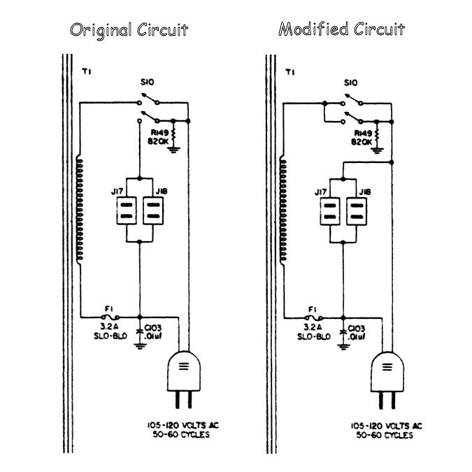
The "Modified Circuit" probably closely resembles the AC wiring inside the tape deck.
It is possible that the AC Power Switch {S10} is on the secondary winding of the T1 Transformer,
and your seeing the Primary winding when you do a continuity test.
Or the AC Power Switch {S10} was closed, when you did the continuity test.
Thus, why your reading a dead short.
Signed: Janitor Tzap
This will help.
The "Modified Circuit" probably closely resembles the AC wiring inside the tape deck.
It is possible that the AC Power Switch {S10} is on the secondary winding of the T1 Transformer,
and your seeing the Primary winding when you do a continuity test.
Or the AC Power Switch {S10} was closed, when you did the continuity test.
Thus, why your reading a dead short.
Signed: Janitor Tzap
Re: Hot / neutral?
What is the relationship of the modified power circuit to the circuit problem? Switched outlets, or not, there appears to be no short towards the transformer, unless what is being read is the transformer's normal primary!
An ohmmeter can be misleading here because DC ohms and AC impedance are different critters. Plus, do you even know what the 'Normal' transformer winding DC resistance is?
A transformer could have shorted turns, primary or secondary and an ohmmeter will not find it. Dynamic testing under power sure will find that problem though!
Often overlooked is the fact that any transformer can step up or down voltage. A very easy method to test all windings of a transformer is to apply a low voltage to one transformer winding then check all the other windings for voltage. A bad winding will be quite obvious since the voltage will be greatly reduced.
So, as previously said.....
"If you want to safely do power on tests put a 120 V light bulb in series with the power line. 100 Watt is a good start. It saves the three F's. .Fires, Fuses and Frustration!"
If there is a dead short, the lamp sees the 120v and lights at full brightness. Normally the lamp would come on bright for a second or two until the power supply capacitors are charged then it should glow dimly. You can make some measurements, being mindful of the expected lower voltage readings and the touch, smell and look tools all work well here too!
If you have a large wattage lamp, you can often run the equipment without any serious low voltage issues. Compare the equipment wattage rating as a guide. For example, a power amplifier may distort at high levels but that is expected since the test lamp reduces the available power to the amplifier.
I have a box with a lamp holder, a DPDT power switch and a bypass switch that allows the series lamp or full voltage to be applied to a unit under test. I also have miniature lamp sockets with clips for jumping fuses in low voltage systems. and a couple of adapters for the blade type auto fuses. It sure saves the 3F's!
This idea goes way back to the days of troubleshooting house wiring with glass plug fuses. A 'test lamp' screwed right into the fuse socket!
Some of the really simpler things are still valuable.
Len
“To invent, you need a good imagination and a big pile of junk.” (T. Edison)
"I must be on the way to success since I already have the junk". (Me)
“To invent, you need a good imagination and a big pile of junk.” (T. Edison)
"I must be on the way to success since I already have the junk". (Me)
Who is online
Users browsing this forum: No registered users and 66 guests